Traffic Line Lanes
Enter the traffic (line) lanes for moving load analysis.
From the Main Menu select Load > Moving Load > Traffic Line Lanes.
![]() To enter new or additional traffic line lanes
To enter new or additional traffic line lanes
Click ![]() .
.
![]() To modify previously entered traffic line lanes
To modify previously entered traffic line lanes
Select the traffic line lane to be modified in the dialog box and click ![]() .
.
When ![]() is clicked, the selected lane elements will be displayed on the screen.
is clicked, the selected lane elements will be displayed on the screen.
![]() To delete previously entered traffic line lanes
To delete previously entered traffic line lanes
Select the traffic line lanes to be deleted in the dialog box and click ![]() .
.
Data entry method when ![]() is clicked
is clicked
 Lane Name
Enter the name of a traffic line lane.
Traffic Lane Properties
![]() Eccentricity
Eccentricity
Enter the eccentricity of a traffic line lane relative to a traffic line lane element.
(-) Negative represents the left side of the traffic line element and vice versa.
Note
Traffic line lane element is defined as the reference frame element from which the eccentricity is measured.
Wheel Spacing
Enter the spacing between the wheels. For influence line analysis, the program automatically applies a load equal to "Load ÷ no. of wheels" to each wheel.
|
|
|
|
Truck Load |
Lane Load |
For influence line analysis, Uniform Lane Load is loaded to each wheel as a uniform line load, which is the load per unit length divided by no. of wheels. For influence surface analysis, Uniform Lane Loads are applied as uniform area loads acting on the traffic lane surface.
For influence line analysis, Concentrated Lane Load divided by no. of wheels is applied to each wheel. Concentrated Lane Load needs to be applied as a uniform line load perpendicular to the traffic line lane, but this is not supported in influence line analysis using beam elements. For influence surface analysis using plate elements, Concentrated Lane Load divided by no. of wheels is applied to each wheel. Applying Concentrated Lane Load as a uniform line load is currently not available.
Lane Width
Enter the carriageway width. This value is used to consider a single lane bridge based on the clause 207.4. of IRC: 6-2000. This clause states when the carriageway width of a bridge is less than 5.3 m, the number of lanes for design purposes is '1.' When the user defines a Sub-Load Case in Load > Moving Load Analysis Data > Moving Load Cases and the Number of Loaded Lanes is '1,' midas Civil automatically calculates the remaining width of the carriageway.
Impact Factor
Enter the impact factors for the entered traffic line lane elements.
Span Length
Enter the length of the span to calculate the Impact Factor automatically (Please refer to Analysis > Moving Load Analysis Control). The user is required to enter the span length for each element according to the span where the element is located.
Eccentricity of Vertical Load to consider Cant
The eccentricity of loading with respect to the center-line of the track.
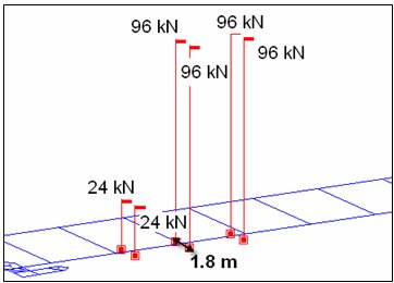
The effect of cant, relative vertical distance between the uppermost surface of the two rails at a particular location along the track may be considered by taking the eccentricity of loading with respect to the center-line of the track, which will result in the increase in the wheel load on the inside of the curve and a concomitant decrease in the outside wheel load.
The wheel load reactions, RL and RR are calculated by summing moments about Point O and enforcing equilibrium.
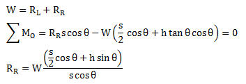
If the slope is 5%,  (s = 2.0m, h = 2.0m)

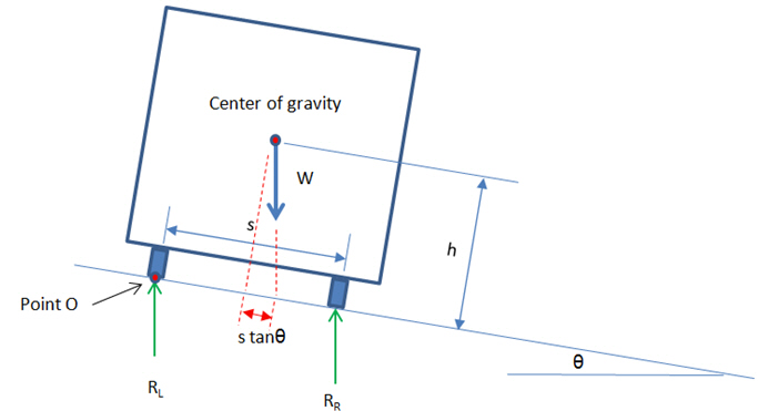
Figure 1. Effects of cant of the wheel load reactions
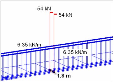
This can be simulated by applying the eccentricity of vertical loads. In the above case, the associated eccentricity can be calculated by summing moments about the center of gravity as follows:
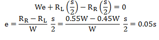
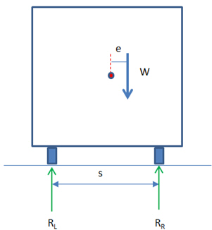
Figure 2. Eccentricity of vertical loads
Note 1
This function works with the Rail Traffic loads only. Road Bridge and Permit vehicle are not supported for this function. The supported trains are as follows:
Load Model 71, Load Model SW/0, Load Model SW/2, Unloaded Train, HSLM A1 ~ A10, HSLM B
Note 2
Sign convention of eccentricity: The positive value means that the sum of vertical loads (W) is applied to the right side of the track by the amount of eccentricity with respect to the center-line of the track. The green arrows represent the direction of lane.
Traffic Lane Optimizations
In the previous versions (up to midas Civil 2015 V1.2)
When a traffic lane (line lane or surface lane) is defined, the moving load is applied with the vehicle loads located in the center of the lane only. In other words, the transverse floating of vehicle loading within a lane is not available.
However, the most critical member forces, stresses or reactions at each location may not always result with the vehicle loads placed in the middle of traffic lanes. In other words, the worst effect of vehicle placement is not guaranteed by placing the vehicle loads in the middle of the lane only.
(Users need to manually define additional lanes in order to obtain the worst effect of vehicle placement in the transverse direction.)
Current versions (midas Civil 2015 V2.1 and up)
When the “Traffic Lane Optimization” option is checked on, midas Civil transversely floats the vehicle load within the lane and obtains the worst effect of the vehicle placement for each element.
Instead of every possible location, the middle (existing), left-end and right-end positions of the lane width are considered for the efficiency of analysis run time.
In other words, with this option, each vehicle has two additional positions, the left and right ends, within each lane.
Users can define vehicle loads and traffic lanes the same way as in the previous versions. With the “Traffic Lane Optimization” option checked, the worst transverse effect of the moving load analysis can be obtained for each element.
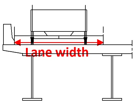
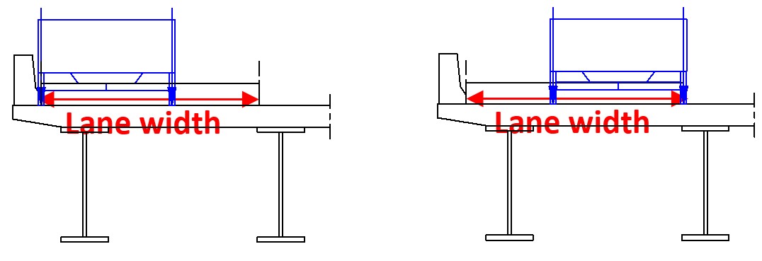
Existing vehicle locations (the middle) Additional vehicle locations considered (left-end, right-end)
Note
At the moment, this feature is not supported for India, Taiwan and Australia code.
Vehicular Load Distribution
Assign the means of distributing the vehicular load.
Lane Element: Apply loads to the traffic line lane elements reflecting the eccentricity.
When defining the lanes with lane element type, the vertical load components (vehicle loads) and the moment due to eccentricity is assigned only on the line lane element. Even though the lanes can be located on cross beam elements, if the lane element type is selected, then the distribution effect for the cross beam analysis will not be considered.
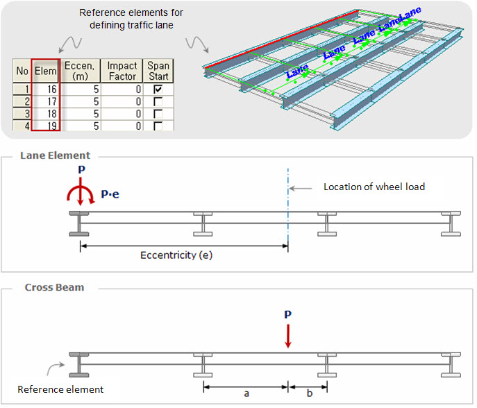
Cross Beam: Apply the traffic load to the cross beams.
When using Cross Beam type, the eccentricity is used only for locating the lanes from the line lane element. The vehicle loads are distributed to the girders by cross beam elements defined as a Cross Beam Group. If the user is modeling a bridge having multiple girders, the Cross Beam type is recommended for vehicular load distribution.
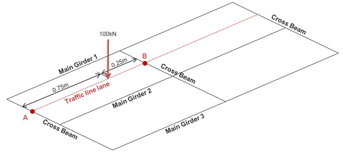
For example, an axle load of 100kN is located as shown below. Then, concentrated loads, 25kN and 75kN, are applied to point A and point B respectively. The cross beams themselves are loaded. The smaller spacing between cross beams gives the more correct results for the moving load analysis.
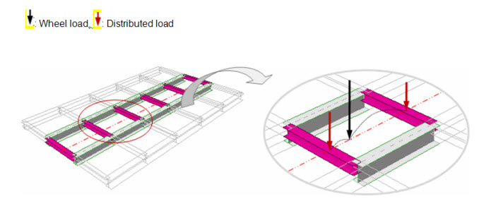
Cross Beam Group: Specify the name of the Structure Group to which Cross Beams are assigned. A wheel load is distributed to adjacent cross beams as shown below.
Note
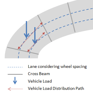
When Cross Beam option is selected in the curved bridge, the cross beam spacing must be dense enough (ex. 0.5m). If the cross beam spacing is large, the program can have a problem in detecting the adjacent cross beam elements. This problem can occur only when the radius of curve is relatively small comparing to the bridge length.
Skew: Specify the Skew Angles at the Start and End of the bridge.
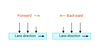
Moving Direction
Assign the direction of traffic loads.
Forward: Consider the direction from the Start to End only.
Backward: Consider the direction from the End to Start only.
Both: Consider the both direction.
Selection by
![]() 2 Points: Beam elements in a line defined by 2 points are assigned as traffic line lane elements. The first point becomes the Start point.
2 Points: Beam elements in a line defined by 2 points are assigned as traffic line lane elements. The first point becomes the Start point.
![]() Picking: Assign the traffic line lane elements with the mouse. The location of the first-assigned element becomes the Start point.
Picking: Assign the traffic line lane elements with the mouse. The location of the first-assigned element becomes the Start point.
Number: Enter the element numbers pertaining to the traffic line lane elements. The location of the first-assigned elements becomes the start point.
Operations
The data entry is reflected when Selection by Number is selected.
Add : Add to the selected traffic lane elements with the specified eccentricity and impact factor.
Insert : Insert the selected traffic lane elements in between the previously entered traffic lane elements.
Delete : Select the traffic lane elements at the bottom of the dialog box and delete.
Note
The traffic line lane must be consecutively entered in the direction of the moving path of the vehicles. When assigning elements with 2 points or Picking [Add] or [Insert] button need not be clicked.
![]() Span Start
Span Start
For multi-span bridges, select the starting element of each span to distinguish spans. This is used to calculate the maximum negative moment of a continuous bridge due to DL.
![]() When Transverse Moving Load is selected in the Moving Load Code
When Transverse Moving Load is selected in the Moving Load Code
![]() Scale Factor
Scale Factor
Enter the scale factor for the application of transverse moving loads.
![]() Selected by
Selected by
![]() 2 Points: Beam elements in a line defined by 2 points are assigned as traffic line lane elements. The first point becomes the Start point.
2 Points: Beam elements in a line defined by 2 points are assigned as traffic line lane elements. The first point becomes the Start point.
![]() Picking: Assign the traffic line lane elements with the mouse. The location of the first-assigned element becomes the Start point.
Picking: Assign the traffic line lane elements with the mouse. The location of the first-assigned element becomes the Start point.