|
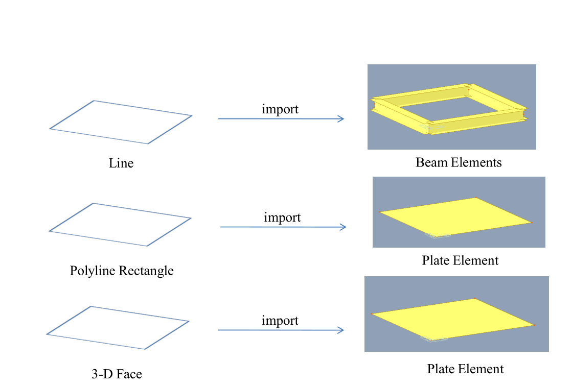
Start > File > Import
Q1. In what form is the line, polyline and solid model in AutoCAD imported into midas? Is line imported as a beam and so on.
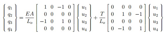
Structure > Wizard > Cable Stayed Bridge
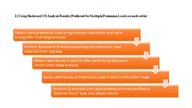
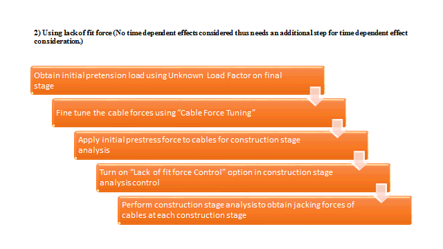
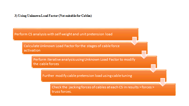
Q1. There are different tutorials for Construction Stage Analysis of Cable Stayed Bridges mentioning different methodologies. Which method should I adopt and how?
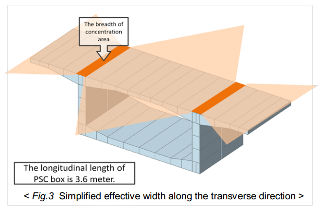
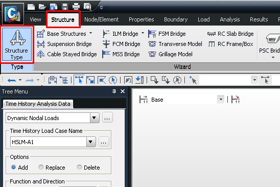
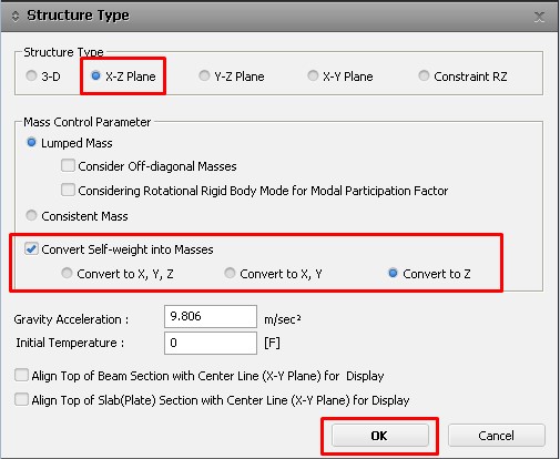
Structure > Wizard > Transverse Model
Q1. I am working with the "Transverse analysis model wizard" of midasCivil. I already did the model of the bridge I am working on, using PSC elements. The girder is a simple box which has to be analyzed longitudinal and transversely for its subsequent design. As far as I could see, both analysis (long. and trans.) are made separately by midasCivil, then when I use the "Transverse analysis model wizard" it creates a 2D model of the transverse section selected. At this point, I am having issues with the definition of the moving loads. The input data is simple; but not very good explained in the on-line manual. For instance, when defining the vehicles, there is a value "Distribution width W:" I don't know what it refers to. Additionally, I need to define 3 vehicles and get the involvement of these 3 loads; but it's not possible to define more than 1 vehicle. On the other hand, I am working with the load cases LM1, LM2 and FLM2 (Lorry 3) of the Eurocode. Consequently, I don't know how to define these load cases for the analysis of 1m long of the transverse section in midasCivil. I would like to have more detail explanation and an example of application of these loads. In the same way, I did a hand calculation using Homberg charts and FEM to get the evolvement of the moments in the transverse section, but the results are completely different from those given by midasCivil. I attach the file I am using with the moving load LM1 of the Eurocode. I am not sure about if I did it okay because I assumed many things to define the loads. It suposse to be applied max. 2 lanes of loads, the first one using a load for each wheel equal to 150 [kN] and the second one using a wheel load equal to 100 [kN]. Please check the Eurocode 1991-2, pag. 35.
Node/Element > Create Elements
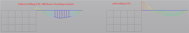
Q1. Can someone explain the idea behind Drilling DOF in detail?
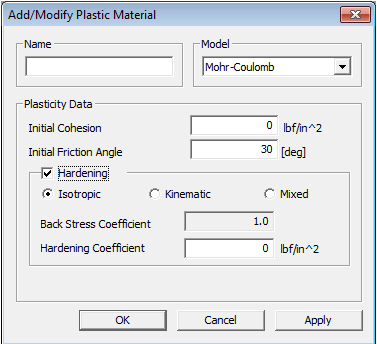
Model > Properties > Plastic Materials
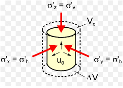
Q1. How can you simulate nonlinear behavior of concrete with plate / solid elements ?
Properties > Section > Section Properties
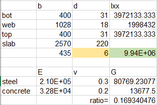
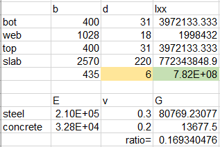
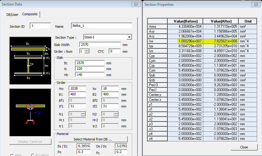
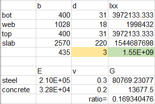
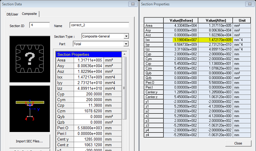
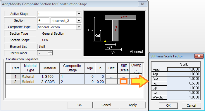
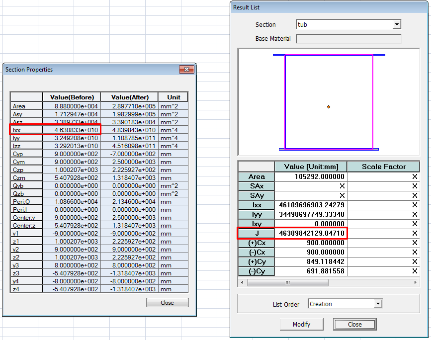
Q1. Why is there a significant difference in the torsional resistance (Ixx) when generating a composite section in Civil and in SPC?
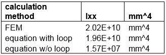
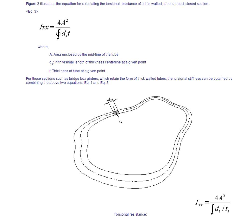
Q2. What is the difference between FEM and Equation options when importing sections from *.SEC files and why is the torsional resistance of my section so low?
Q3. When I try to generate a tapered section between two pre-defined sections (both imported from Section Property Calculator), software gives an error message and fails to generate the tapered section. Why?
Q4. The principal one is the calculation of the torsional properties. When we use it we calculate them and we modify the values.
- Regarding to torsional properties we have noticed that they do not have geological effects (no creep) -> we have added this item to the "wish list".
- Calculation of torsional inertia -> we do not know how Civil does it.
I am sending you an example of a composite "Composite section t stub" automatic defined by Civil in which properties in steel part and composite are nearly the same, and calculating it the composite one does not have the same value.
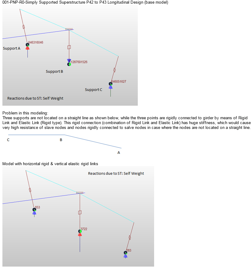
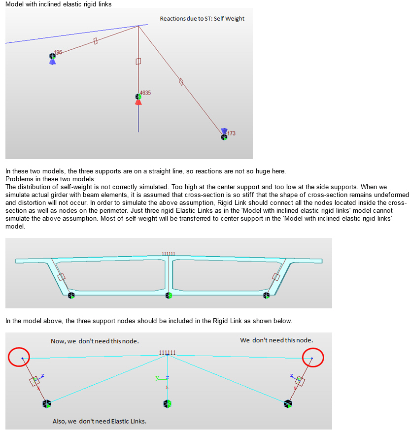
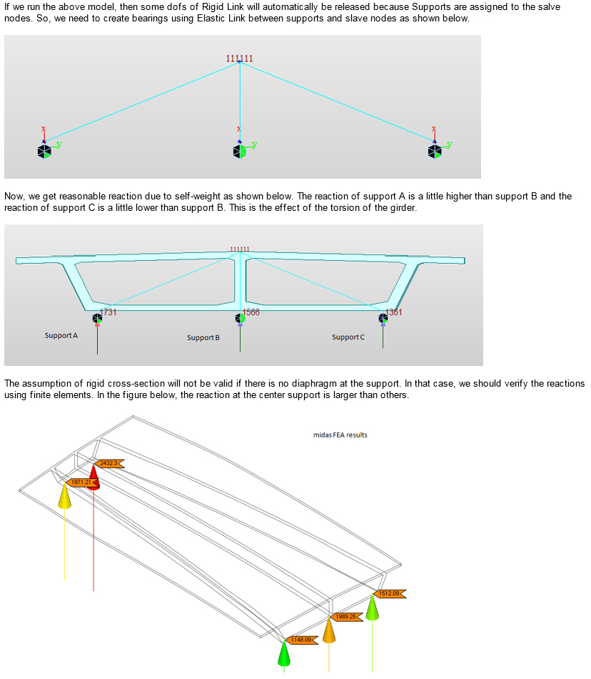
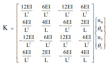
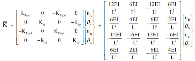
Boundaries > Rigid Link
Q1. If the horizontal and vertical link assembly is changed to inclined link assembly, the vertical reactions change. Why ?
Boundaries > Beam End Release
Q1. Why member force with partial fixity is different from the value of "original member force x scale force"?
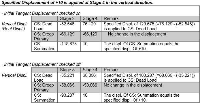
Load > Static Loads > Specified Displacements of Supports
Q1. Can you explain why the sum of reactions due to the ‘Specified Displacement’ load case in model file is not equal to zero. It is close to zero but not exactly. Does midas have any setting where the precision can be controlled by the user?
Q.2 I assigned a fixed support to the pier of my bridge model. To this fixed support, I specified a displacement of +0.5m (z- direction) in Construction Stage2. When I deactivated the specified displacement load case in CS3, I expected the support to come back to its initial position, i.e. the position before activating specified displacement. But after deactivating the specified displacement, the support didn't move and remained at z=0.5m. Why?
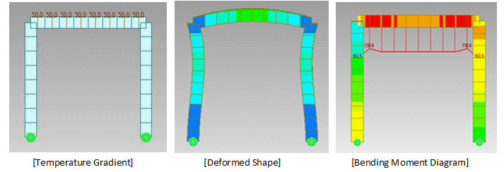
Load > Temp./Prestress > Temperature Gradient
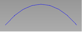
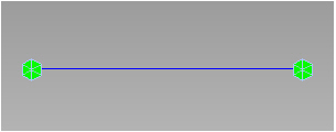
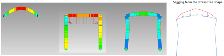
Q1. I applied the Temperature Gradient load of 50 °C (25 °C at the top and -25 °C at the bottom, linear variation in between) to the horizontal member and got the deformed shape of horizontal member in hogging (upwards). I would like to know why the bending moment diagram is sagging (downwards), while the member is deflected in hogging (upwards).
Load > Temp./Prestress > Beam Section Temperature
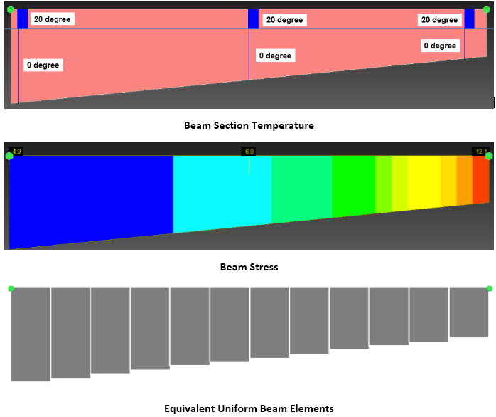
Q1. How Beam Section Temperature load should be applied for tapered section as we cannot define different temperature variation for i-end, middle, and j-end separately?
Load > Temp./Prestress > Tendon Property
Q1. What are the considerations in the program regarding external tendons?
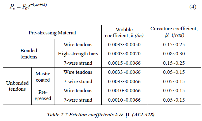
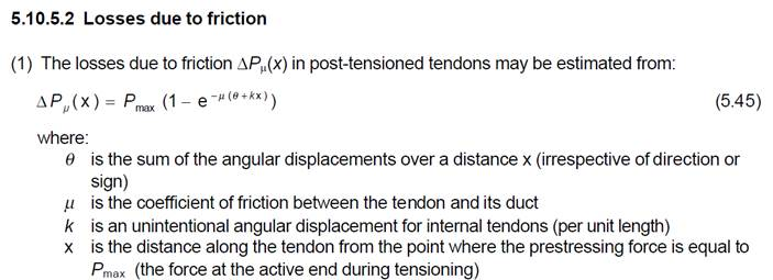
Q2. What is the Wobble Friction Factor and how does it relate to the "unintentional angular displacement"-factor (k)?
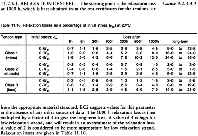
Q3. What is the consideration in the software for relaxation loss calculation when Eurocode is selected?
Load > Moving Loads > Define Moving Load Case
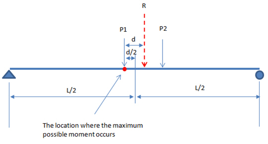
Q1. Two wheel loads with the same amount of loading passes along the simple span. After performing moving load analysis, the result of bending moment shows that the maximum bending moment does not occur at the center of span. I do not understand why?
Load > Moving Load Analysis Data > Traffic Surface Line
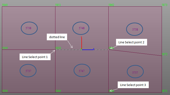
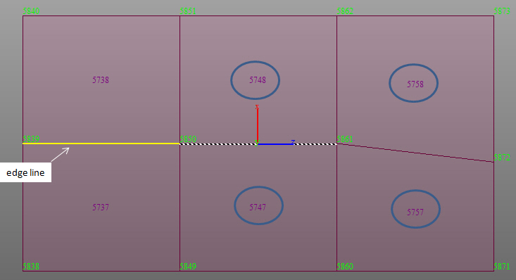
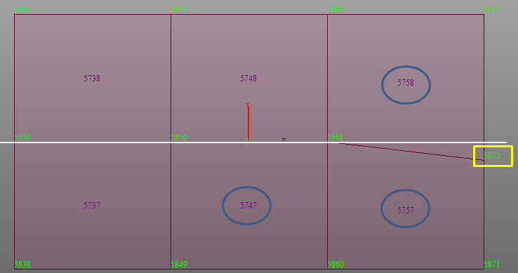
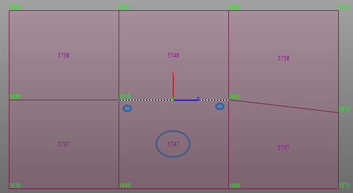
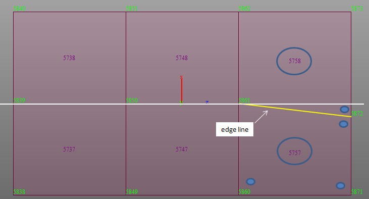
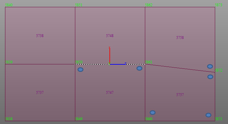
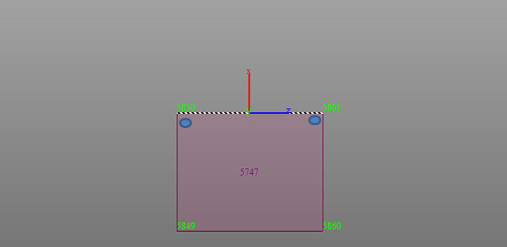
Q1. A surface lane is defined along the arch bridge model but it appears that the surface lane is only applied over a part of the arch as shown below. Why?
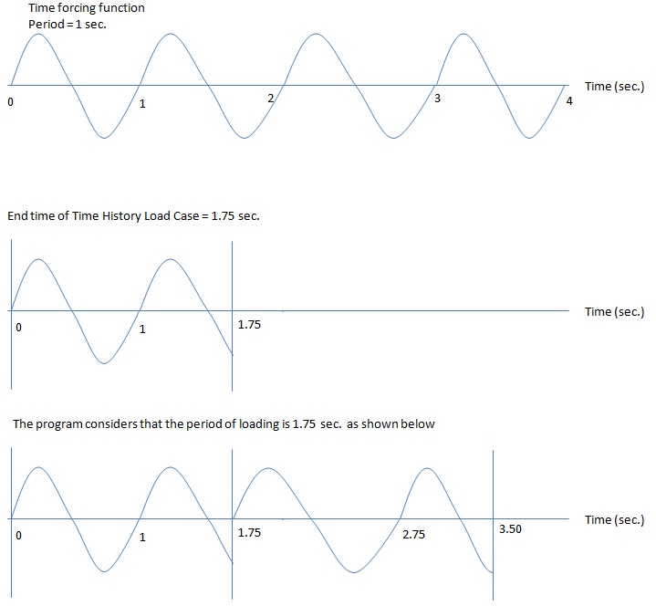
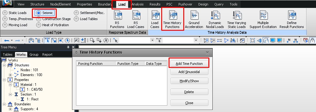
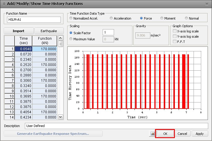
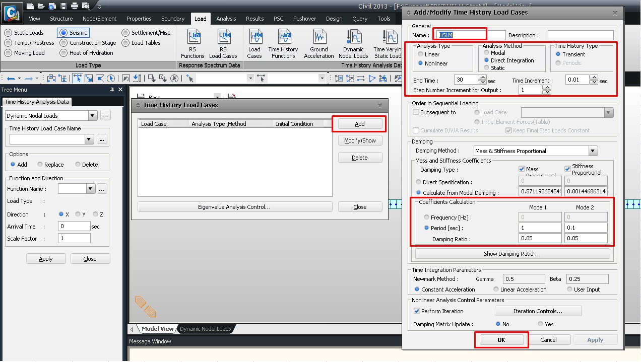
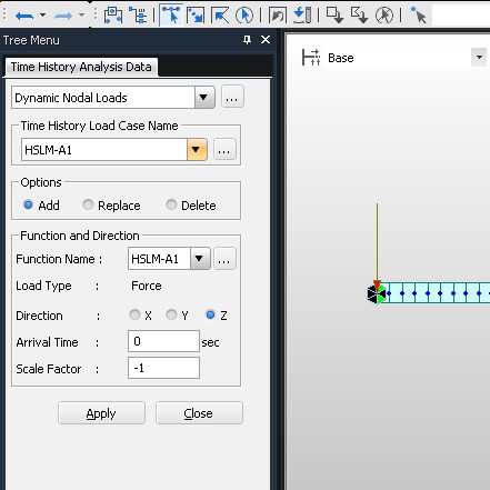
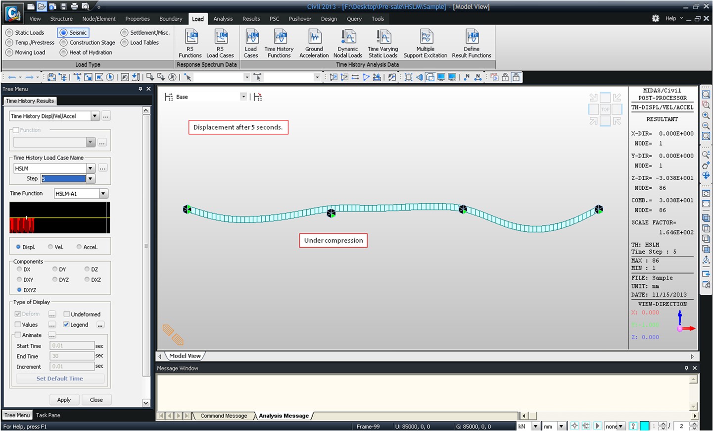
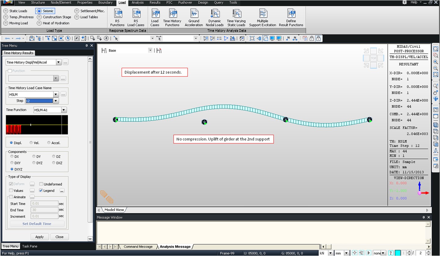
Load > Seismic Load > Time History Load Case
Q1. Just to illustrate the question I had on periodic TH load case. I am looking at TH load case #3 using the crowd loading. The load has a frequency of 2.98Hz, so a period of t=0.33557s. I have specified End Time as 13.4 seconds (which has remained from the time it takes for the walking pedestrian to cross the bridge, but is irrelevant for the crowd). When I look at Displacement Contour for THmax: Crowd, the max value is 2.82. If I change the End Time of the load case to the period of the forcing function (0.33557), the result comes out as 2.6: Which one is correct? Or am I reading something wrong? From the online manual it sounds as if the correct definition is 0.33557, but then the result is lower than the full time, which is not on the safe side.
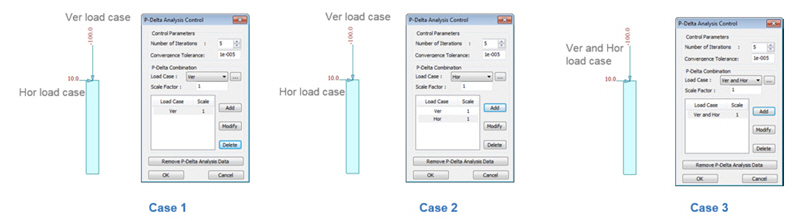
Analysis > P-Delta Analysis Control
Q1. Which load cases do I have to add in “P-Delta Combination”? The result of the load combination which doesn’t include vertical load case was changed after performing P-delta analysis.
Analysis > Buckling Analysis Control
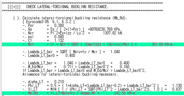
Q1. Can midas Civil consider second-order incorporating lateral torsional buckling directly?
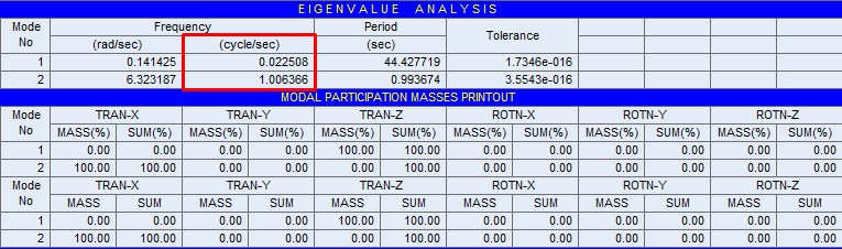
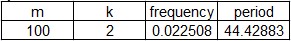
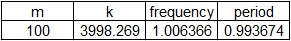
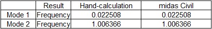
Analysis>Eigenvalue Analysis
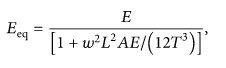
Q1. Please give me your recommendation regarding the eigenvalue analysis of suspension bridge. How can I make eigenvalue analysis of suspension bridge taking into account both axial stiffness based on the Ernst equation (sagging effect) and geometrical stiffness in cable?
Analysis > Construction Stage Analysis Control
Q1. There are construction stage load cases, namely, “creep primary”, “creep secondary”, “shrinkage primary” and “shrinkage secondary”. What are the meaning of “primary” and “secondary”, their differences and application?
Q2. If I look to member forces to design an element, should I look to primary or secondary?
Analysis > Perform > Import Analysis Result
Q1. I try to import the analysis results(*.sar file) into midas Civil.The following error message is displayed:"AN INPUT ERROR OCCURRED AT LINE : 1 PLEASE CHECK INPUT DATA" I think I am making some mistake in the format of sar file. Please advice me.
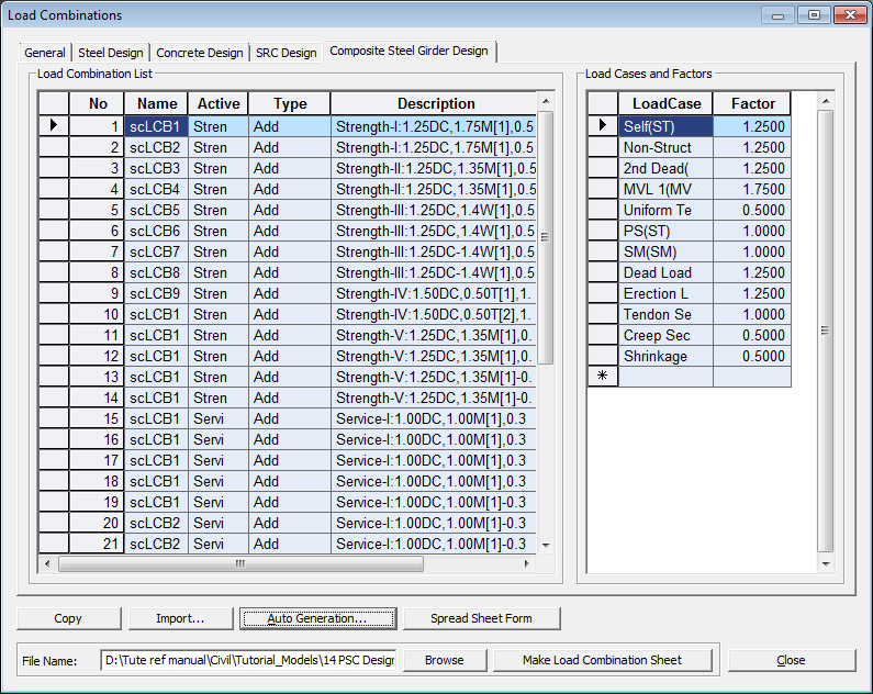
Results > Combination > Load Combination
Q1. I have a question regarding the load combination import from one model to another in midas Civil. I looked for the procedure in the online manual, but I am not sure of how to generate the .lcb file. What is the procedure of importing or pasting a load combination?
Results > Forces > Beam > Forces
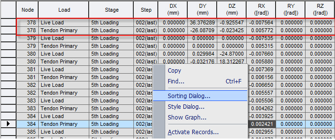
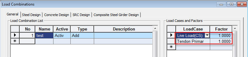
Q1. How can I obtain the results for the summation of CS:Live Load and CS:Tendon Primary only?
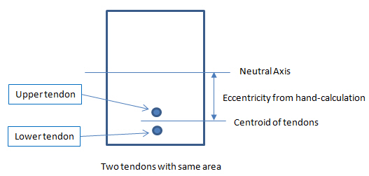
Q2. We are comparing tendon primary results for a bridge. The bending moments produced by the pre-stressing tendons on the centre part of the beam do not match with our hand calculations. We found out a small difference on the centre of gravity of the beam that leads to a significant bending moment variations. Could you please explain why the centre of gravity of the section (concrete + pre-stressing steel) does not match with our calculations?
Results > Local Direction Force Sum
Q1. We have a problem with “Local Direction Force Sum”. Please take, for example, the combination 15, the element 70324 and the LDFS named "1elem - X verso il basso". If I run eigenvalue analysis with 100 frequencies some results of LDFS are incorrect, while if I run eigenvalue analysis with 2 frequencies all the results of LDFS are correct. We have attached a file with calculations and the model.
Q2. The results of Local Direction Force Sum of same position are different between the following two cases: Case 1) Six elements are activated in the model view. Case 2) One element is activated in the model view.
Results > Mode Shape > Vibration Mode Shapes
Q1. I am trying to model a 3span post tensioned girder bridge. When I perform the Eigenvalue analysis with ends of the piles pinned, I get 93% mass participation in X & Y direction. But, when I assign point springs supports to represent soil structure interaction, the mass participation drastically reduces to 60%. I expect at least 90% mass participation within 10 modes. Please explain.
Results > Moving Load > Moving Tracer > Beam Forces/Moments
Q1. In case of AASHTO code, for the moving load analysis, in case of Grillage model of curved bridge, when we trace the vehicle for the maximum negative moment i.e. in accordance with the Lane Support Negative Moments, we do not get the proper vehicle position as per the code. Maximum negative values when compared to other software is coming somewhat less. Why?
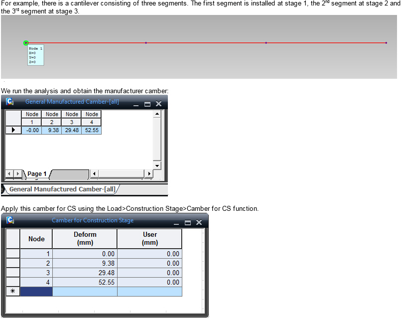
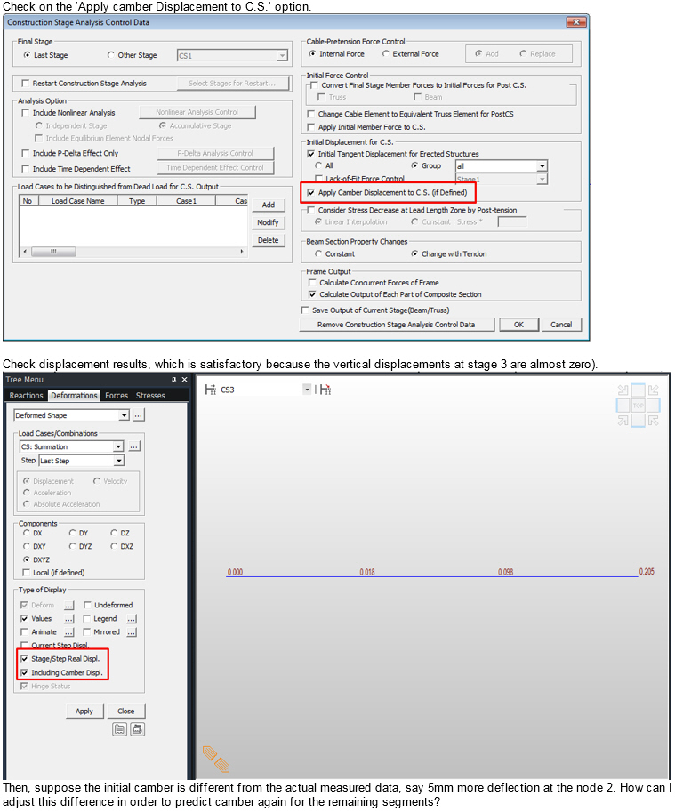
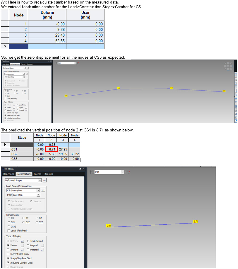
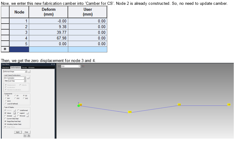
Results > General Camber
Q1. I got the camber using General Camber. Suppose measured camber during actual construction is different from the predicted camber by software. How can I adjust the error?
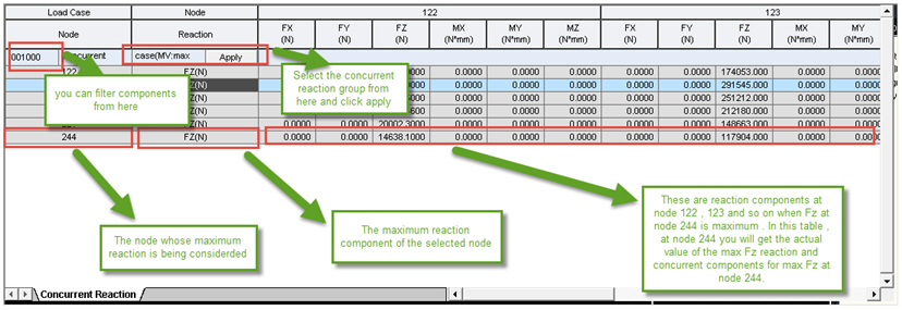
Results > Result Tables > Concurrent (Max/Min) Reaction
Q1. I could not understand how concurrent reactions are tabulated. May you please explain what vertical column and horizontal row stands for? For a specific load case which values should I use?
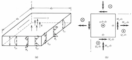
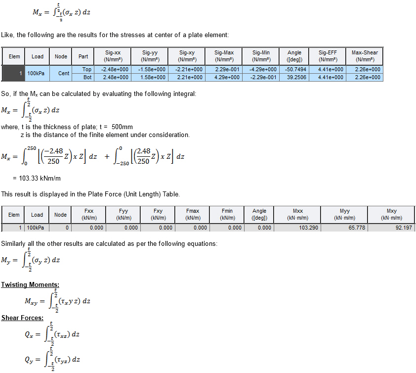
Results > Result Tables > Plate > Force & Stress
Q1. How can I obtain the results for Plate Force (Unit Length)?
Results > Result Tables > Tendon > Tendon Arrangement
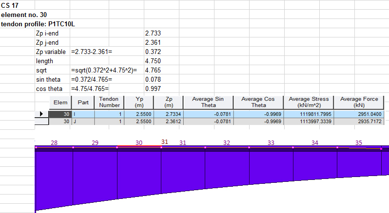
Q1. Could you explain the avg. sin and cos theta in the table? Why the values are the same at two nodes with different thetas? Where to apply the sin and cos theta, especially in tapered sections?
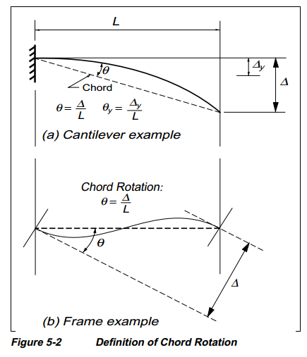
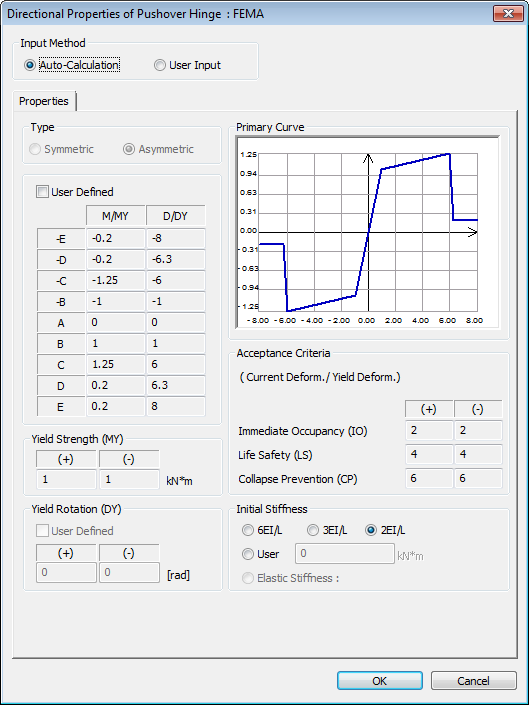
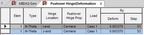
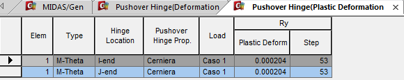
Pushover > Pushover Hinge Result Table > Deformation
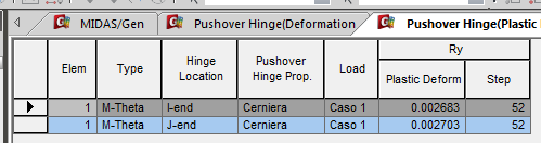
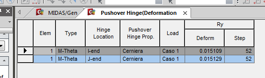
Q1. Thanks for your immediate reply but it generates other doubts. I have attached another file where i go in Plastic field. Now the applied moment is 90 KN. The value of Load Case type ST is correct; it is exactly ML/EJ = 0.006529 > OK. But we don't understand the value 0.01172 for Load Case type PO. In fact, if this is the rotation of the node, how it is possible that it is less than the rotation of the hinge in J-end, which is 0.015129?
Design > RC Design > Serviceability Parameters
Q1. What is the Deflection Amplification Factor in Serviceability Parameters?
Design > RC Design > Concrete Code Design > Beam Design
Q1. For Shear Design as per Eurocode2, the load combination being used for design is not the one with maximum shear force. Why?
Design > Steel Design > Transverse Stiffener of Box Section
Q1. How does the presence of transverse stiffener affect the design? It affects which formula?
Pushover > Perform Pushover Analysis
Q1. A bridge model file generates an error when performing Pushover Analysis.
"AN ERROR OCCURRED IN UNPKID NODE: 2215 DIR: 1 Stop - Program terminated." The model has 2214 nodes only. Still the error is at node 2215. Why?
Tools > General Section Designer
Q1. GSD is hanging up when I perform the design. Why?
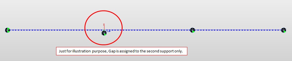
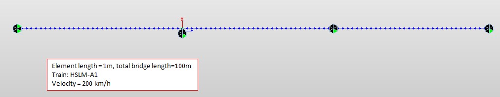
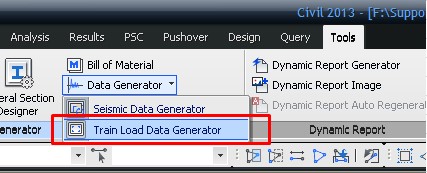
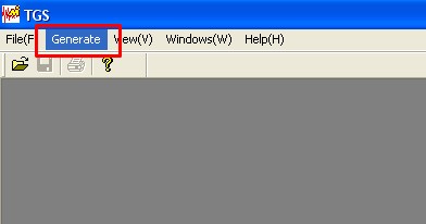
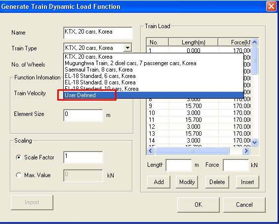
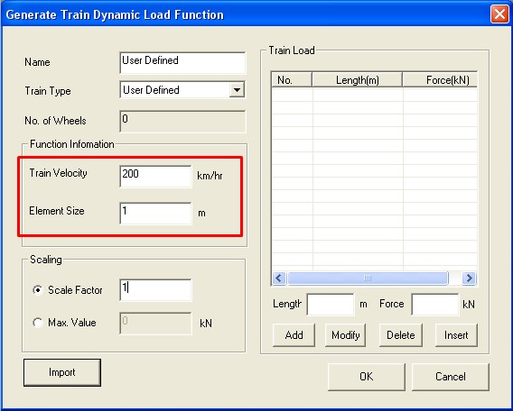
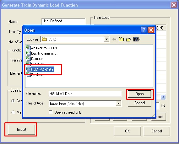
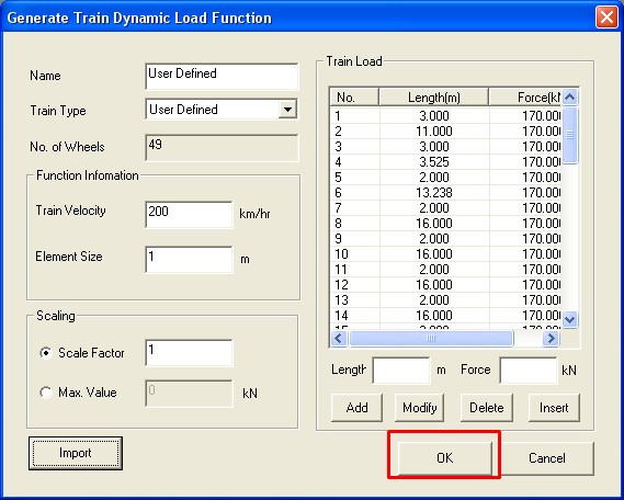
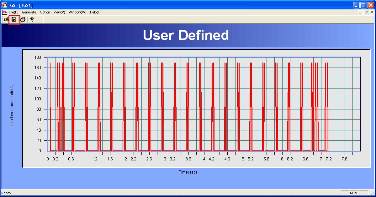
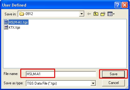
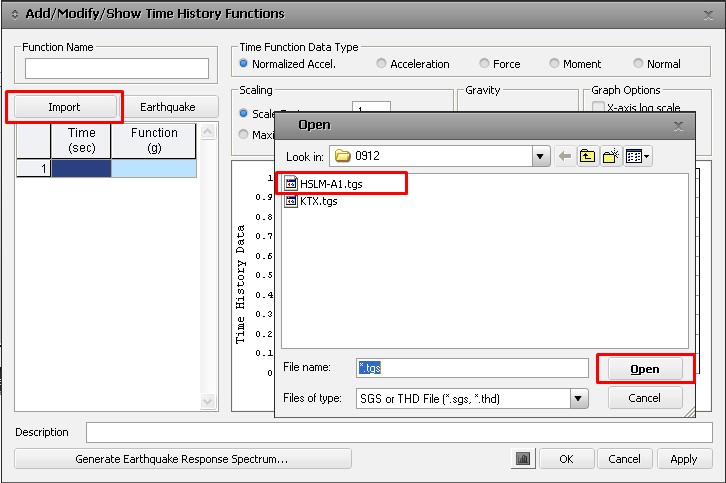
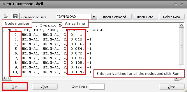
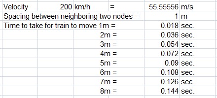
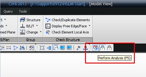
Tools>Data>Generator>Train Load Data Generator
Q1: How can I perform train-structure interaction in midas with the effects of the compression-only bearing? Could you show me the whole process, i.e. defining train loads, train speed?
Load > Temp/Prestress > Tendon Property
Q1. What is the Wobble Friction Factor and how does it relate to the "unintentional angular displacement"-factor (k)?
Q2. What is the consideration in the software for relaxation loss calculation when Eurocode is selected?
Appendix > MCT File Quick Reference
Q1. In *LOADCOMB command, could you please explain what the following are: bES, iSERV-TYPE and nLCOMTYPE?
|