Prestressed Composite Bridge Wizard (Layout)
About Pre/post tensioned composite girder bridge wizard
A precast girders are fabricated off-site and then transported and erected at the job site. It can facilitate rapid construction of a bridge and have been proved to be economical.
A spliced girder is fabricated in several relatively long pieces (i.e., girder segments) that are assembled into a single girder for the final bridge structure. The girder segments are post-tensioned continuously in order to reinforce the connection between the segments.
Both the precast girder and splice girder are a precast prestressed concrete member and can be applied for a simple or multiple span bridges.
The fundamental objective of using the Pre/Post-tensioned composite girder bridge wizard (hereafter “PC Girder Wizard”) is to generate 3D finite models with ease in a relatively short time.
A precast and splice girder bridges that are straight, curved, and/or skewed can be modeled with substructures. Also, the wizard provides various modeling approaches (i.e. grillage approach, full plate approach, etc.). Loadings and construction sequences can also be defined based on the straightforward inputs and intuitive interface of the wizard.
The wizard is a very flexible tool that allows modification at any point of the initial data entering. Any data entered in the wizard can be saved as a file and opened and reused in future.
Wizard configurations
The wizard consists of the five main tabs.
The first tab (Layout) is for defining the basic geometry of a bridge and support properties. The second tab (Section) is for defining the material and section properties and the locations of girders and beams. The third tab (Tendon) is for defining the all kind of pre/post tendon with simple inputs. The fourth (Load) and fifth tab (Construction Stage) are to define the load and construction stage conditions.
All Wizard input can be saved into a “*.wzd” file format.
 : Open an existing wizard file saved as *.wzd file type in the PC Girder Wizard. By opening the file users have worked on before, users can re-execute, check, and modify the previously entered data.
 : Save the data entered in the PC Girder Wizard as the *.wzd file type.
Using the wizard, full steel composite bridge models can be generated. Define the overall layout of the bridge geometry, boundary conditions, etc. in the Layout tab.
From the Main Menu select Structure > Wizard > Prestressed Composite Bridge Wizard > Layout
![]() Girder Type
Girder Type
Select one of the following girder types for the bridge.
Precast Girder Type:
Girder is fabricated off-site and erected span by span.
Splice Girder Type:
Girder is fabricated in several pieces. The girder segments are disconnected at the spliced locations.
The wizard composition is different for each girder type.
![]() Modeling Type
Modeling Type
The deck and girders can be modeled in different modeling approaches: all frame, deck as plates and girder as frames.
All Frame :
Use frame elements for the entire model. This option is ideal for conventional straight bridges and can increase the efficiency of analysis times.
Deck as Plates & Girder as Frames :
Use plate elements to model the deck and frame elements to model the girders.
Note
Depending on the girder type and modeling approach (All frame, Deck as plate, …), the input menus are customized.
Only frame elements are used to model diaphragm and substructures regardless of the modeling approach selected.
![]() Span Information
Span Information
Specify the span length(s) in order.
(e.g. “200, 250, 2@120, 100” indicates that the first through the fifth spans are 200 ft, 250 ft, 120 ft, 120 ft, and 100 ft long each.
The span information is for the Reference Line. If the bridge model is skewed and/or curved, any span information should be taken from the Reference Line position.
Note
Also, the distances of transverse deck element spacing, and distances of intermediate diaphragm (section tab) are based on the Reference Line.
![]() Deck Width
Deck Width
Specify the total deck width of the bridge. The deck width is used to indicate the deck width of the entire bridge. This information is used to create any dummy deck member or to suppress the deck information in the section properties for the Deck as Plates and Girder as Frames modeling types.
![]() Layout offset
Layout offset
Distance between the reference line and the center line of the bridge.
![]() Support Skew Angle
Support Skew Angle
Specify the skew angle of each support position of the bridge in plan (θ deg). The skew angle must be between -75 and 75 degrees.
Select “skew” for the angel type of the transverse deck elements in order to place the diaphragms following this skew angle.
When the reference line has a single radius, the girder type is the Precast, and the girder alignment condition is “Same Spacing”, the reference support skew angle for diaphragm placing is followed instead of each support position of the bridge.
The diaphragms will follow this support skew angle. The transverse deck element will follow this skew angle if the angle type is skew. However, if the girder type if Precast and the girder alignment type is Same Spacing, only the support at the reference line will follow this skew angle
![]() Radius
Radius
Specify the radius for a horizontally curved bridge.
Convex: Convex curvature (center of circle located below the curve)
Concave: Concave curvature (center of circle located above the curve)
![]() Multi-Curve
Multi-Curve
Select Curve Data or Coordinate Data as an input method and click  to input multiple curves
Curve Data: Using the Multi-Curve Advanced option, the curvature can also be defined for a combination of straight and curve geometries.
Plan Curve
Define the horizontal curve(s).
Straight Line: The start and end location of the straight line.
Circular Curve: The start and end locations of the plan curve with specified radius of the curve point.
Transition Curve: The start and end locations of the transition curve with specified radius of the curve point.
Vertical Curve
Station: The station of the vertical curve
ELEV.: The elevation of the vertical curve
Curve Length: The horizontal length of the vertical curve
Bank Rotation
Station: The station of the bank rotation
Super Elevation: The super elevation of the bank rotation.
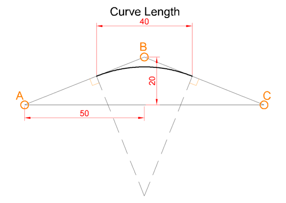
Example
|
|
Station (m) |
ELEV. (m) |
Curve Length (m) |
|
1 |
0 |
0 |
0 |
|
2 |
50 |
20 |
40 |
|
3 |
100 |
0 |
0 |
Coordinate Data: Using the Multi-Curve Advanced option, the curvature can also be defined for a combination of straight and curve geometries.
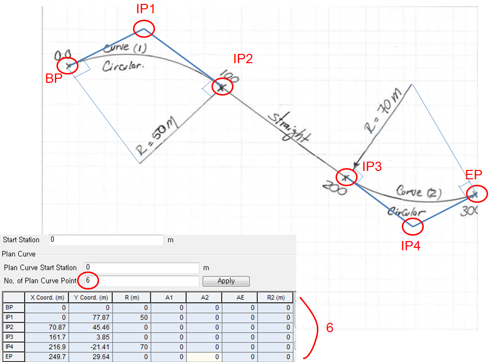
Start Station: The start station of bridge modeling
Plan Curve
Define the horizontal curve(s).
Plan Curve Span Start: start station of plan curve
No. of Plan Curve Point: Number of Plan Curve points. At least two of the plan curve points are required for the beginning point (BP) and the end point (EP). If the bridge has more than one curve or is a combination of curve and straight geometries, the number of plan curve point is equal to or greater than three. If three or greater number is input for the number of plan curve point, additional intermediate points (IP 1 for three plan curve pints, IP 2 for four plan curve points, …)
BP: The beginning point of the plan curve
EP: The end point of the plan curve
IP 1, 2, …: The intermediate points. (IP 1 for three plan curve pints, IP 2 for four plan curve points, …)
X Coord.: the x coordinate of the curve point
Y Coord.: the y coordinate of the curve point
R: The radius of the curve point
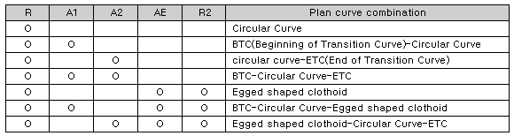
A1: The parameter of BTC(Beginning of Transition Curve)
A2: The parameter of ETC(End of Transition Curve)
AE: The parameter of egged shaped clothoid curve
R2: The 2nd radius of egged shaped clothoid curve
Vertical Curve
Station: The station of the vertical curve
ELEV.: The elevation of the vertical curve
Curve Length: The horizontal length of the vertical curve
Bank Rotation
Station: The station of the bank rotation
Super Elevation: The super elevation of the bank rotation.
Example
![]() Girder Alignment (Precast Girder Type only)
Girder Alignment (Precast Girder Type only)
This information is only valid for the curved precast girder type bridges. In other words, it is only valid with the Radius or the Multi-Curve Advanced checked and defined for the precast girder type.
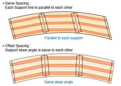
Same spacing
Each Support line is parallel to each other but Support skew angle is different. This option is not supported if the Multi-Curve is defined..
Offset spacing
Support skew angles are the same at each support. The same to each other but each support line is flared from each other (radial shape).
![]() Reference Support
Reference Support
Specify the reference support to define the skew angle. Other supports skew angle are not the same in this case. It is only valid for the same spacing – girder alignment type.
![]() Curved Type (Splice Girder Type only)
Curved Type (Splice Girder Type only)
This option is only valid for the 1) curved 2)Splice Girder Type. In other words, it is only valid when the Radius or Multi-Curve option is checked and defined.
Line Girder Type
Girders are straight regardless the bridge curvature. Slab is modeled following the bridge curvature, if defined; however, the girders are still modeled straight.
Curved Girder Type
Girders are arranged following the bridge curve. The girders are not straight.
![]() Boundary/Substructure
Boundary/Substructure
-
Without Substructure
Substructure is not included in the model. Superstructure and substructure are connected with bearings:
Supports: Bearings are represented by fixed or simple support.
Precast Girder Type: Mostly precast girder are placed simply supported in each span, all the left support is fixed, and the other support is longitudinally free.
Splice Girder Type: Each middle bearing of pier position is considered as a fixed support. Once the position of fixed support is determined, all the other supports in longitudinal direction are considered as free support longitudinally and the other support in transverse direction are considered as free support transversely.
Elastic Link: Bearings are represented by elastic links. Enter the stiffness of bearings in each degree of freedom (Dx, Dy, Dz, Rx, Ry, & Rz) for the abutments and the piers. Click the option to enter different elastic link stiffness for each abutment and piers.
Fixed Support: Select longitudinally fixed support. Longitudinally and transversely fixed bearing is used as a reference point for the determination of the direction of free bearings in the In Line with Fixed Support option.
Direction: Choose the method of determining direction of the free bearings.
Tangential: The restraint-free direction is tangent to the longitudinal axis of the bridge. (i.e. tangent to the curvature of a curved bridge or in the direction of a straight bridge)
Radial: The restraints are freed in the directions from the individual supports to the fixed support.
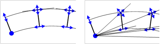
Tangential Radial
-
With Substructure
Substructure is included in the model. Define the following parameters for the Abutment, Elastic Link Stiffness, and Pier. The model includes and models the substructure with this option.
Bearing Type / Elastic Link Stiffness
Abutment
Fixed: Abutment set as fixed support
Elastic Link: Bearings are represented by elastic links. Enter the stiffness of bearings by directions for the abutments.
Same as Pier: Substructure of abutment is modeled same as pier information. But stiffness of bearing can be differently input from pier
Pier
Fixed: Pier set as fixed support
Elastic Link: Bearings are represented by elastic links. Enter the stiffness of bearings by directions for the piers.
Click to enter different stiffness for different each supports in Abutments and piers.
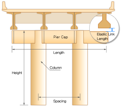
Elastic Link Length: Bearing gaps between the bottom flange of girder and the upper bed of the pier cap are represented by elastic link length.
Pier
Material
Enter the material property to be used in the pier structure.
Click  to add a new material or modify an existing material.
Pier Cap
Check the option if the pier has a pier cap
Section
Select the section to be used for the pier cap.
Click to add a new section or modify an existing section.
Length: Transverse length of the pier cap
Column
Section
Select the section to be used for the pier.
Click to add a new section or modify an existing section.
Height
Enter the height of the pier. Click to enter different heights for different piers.
Spacing
If more than two columns are needed to be defined, specify the distance between the columns. If more than three columns, different spacings are input with commas (e.g. “10, 12” or “2@10”)
Pier Support
Fixed: Fix support is applied to the bottom of the pier.
Spring Support: Spring support is applied to the bottom of the pier.
Spring Stiffness:
Spring Stiffness is activated when the spring support is selected. Enter the horizontal and vertical spring stiffness values.
Click the to input different stiffness for different supports.