Section Manager
Calculate the transformed section properties reflecting tendon and reinforcement. Input of reinforcement for the PSC / Composite Steel-I / Composite Steel-Box Sections becomes more user-friendly.
Stress points can be defined at any position for various cross-sections.
From the Main Menu Select Properties > Section > Section Manager.
![]() Stiffness
Stiffness
Transformed section properties with tendon and reinforcement reflected can be calculated for the various section types (DB, PSC, Tapered Section, Composite Section, General and Composite General Section).
Transformed section properties can be calculated at the various locations (1/4, 2/4, 3/4 Part) of the Section. The placement of tendon and reinforcement can be viewed.
The existing two menus, which are ’r;Section Stiffness Scale Factor’ and ’r;Cross Section Viewer’, have been integrated.
![]() Target Section & Element
Target Section & Element
The Elements are displayed under the assigned Section in the Tree.
Note
Select an Element to input tendon information at an arbitrary location of the Element.
![]() Part
Part
Select the position (i, 1/4, 2/4, 3/4, or j) for which the cross section data of the element is to be produced.
Once the selection is made, the cross section view at that position is updated. In addition, the reinforcement and the tendon at that position is updated to the View and the Table.
![]() View Point
View Point
Select the direction based on which the cross section data of the element is to be produced.
![]() Tendon
Tendon
Display the tendon in the View.
Property Name : Display the Tendon Property Name in the View.
Duct Hall : Display the Duct Hall in the View.
![]() Reinforcement Bar
Reinforcement Bar
Display the Reinforcement Bar in the View.
![]() Stiffness Scale Factor
Stiffness Scale Factor
Boundary Group : Select a boundary group in which the section stiffness scale factor is to be included.
Scale Factor(I, J) : Enter the scale factor for each stiffness component.
I = J : This becomes active only when the selected section is a tapered section and different section scale factors can be applied to I-end and J-end.
Before : Valid for a composite section. The defined scale factors will be used for the calculation of member forces and stresses for the pre-composite section.
After : Valid for a composite section. The defined scale factors will be used for the calculation of member forces and stresses for the post-composite section.
All : If both Before and After are checked on, the defined scale factors will be used for the calculation of member forces and stresses for the pre- and post-composite sections.
Note
If Es/Ec (Long Term) and Es/Ec (Shrinkage) are defined in the Section Data, Boundary Groups for the Long Term and the Shrinkage are automatically generated and the applied scale factors are displayed as well.
Area : Cross sectional area
Asy : Effective Shear Area resisting shear forces in the element local y-axis
Asz : Effective Shear Area resisting shear forces in the element local z-axis
Ixx : Torsional Resistance about the element local x-axis
Iyy : Area Moment of Inertia about the element local y-axis
Izz : Area Moment of Inertia about the element local z-axis
Weight : Weight density used for calculating self-weight
![]() Coordinate
Coordinate
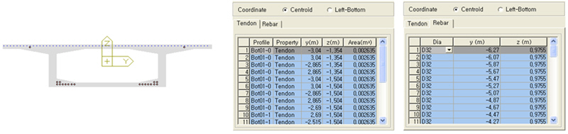
Centroid : Display the locations of tendon and reinforcement with reference to the Centroid of the section.
|
The coordinate system is displayed in the View, based on the Centroid. |
Tendon data is produced based on the Centroid. |
Reinforcement data is produced based on the Centroid. |
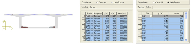
Left-Bottom : Display the locations of tendon and reinforcement with reference to the Left-Bottom.
|
The coordinate system is displayed in the View, based on the Left-Bottom. |
Tendon data is produced based on the Left-Bottom. |
Reinforcement data is produced based on the Left-Bottom. |
![]() Show Stiffness
Show Stiffness
Display the stiffness with Scale Factor, Reinforcement and Tendon taken into account.
![]() Reinforcement
Reinforcement
Longitudinal Reinforcement can be input in various ways (Point /Line/Arc/Circle/Poly Line Types can be input in the Grid).
The way of inputting Reinforced Shear became convenient.
![]() Target Section & Element
Target Section & Element
Display the Target Section about which the reinforcement data is to be produced in the Tree.
![]() Longitudinal Reinforcement tab
Longitudinal Reinforcement tab
Both end part(i, j) have the same reinforcement : Check the box if the reinforcement is identical for both i and j ends of an element. If this option is unchecked, different reinforcement data can be entered under each I and J tab.
![]() Coordinate
Coordinate
Centroid : When Centroid is selected, the Centroid becomes ( 0, 0 ).
Left-Bottom : When Left-Bottom is selected, the Left-Bottom becomes ( 0, 0 ).
![]() Guide Line
Guide Line
If the value is entered, guide lines are generated using the entered spacing relative to the inner and outer lines of the section.
![]() Type
Type
There are five ways of entering Reinforcements (Point, Line, Arc, Circle, Poly line).
Point Type
Center Point (y,z) : Location of the reinforcement
Dia : Diameter of the rebar
Line Type
Input Method A
Ref. Y, Y : Reference point in element local y-direction. Distance can be entered from the centroid or left most position.
Ref. Z, Z : Reference point in element local z-direction. Distance can be entered from the top or bottom fiber of a section.
Num: Number of rebars
Dia : Diameter of the rebar
Input Method B
Starting Point(y,z) : Starting point of the reinforcements
End Point (y,z) : End point of the reinforcements
Num : Number of rebars
CTC : Spacing of rebars
Edge Bar : Specify whether to place the rebar at the edge or not
Spacing : Spacing of rebars
Dia : Diameter of the rebar
Arc Type
Starting Point(y,z) : Starting point of the reinforcements
Passage Point(y,z) : Intermediate point of the reinforcements (1 point)
End Point (y,z) : End point of the reinforcements
Num : Number of rebars
CTC : Spacing of rebars
Edge Bar : Specify whether to place the rebar at the edge or not
Dia : Diameter of the rebar
Circle Type
Center Point(y,z) : Center point of the reinforcements
Radius : Radius of the reinforcements
Num : Number of rebars
CTC : Spacing of rebars
Dia : Diameter of the rebar
Poly Line
Starting Point(y,z) : Starting point of the reinforcements
Passage Point(y,z) : Intermediate point of the reinforcements (n points)
End Point (y,z) : End point of the reinforcements
Num : Number of rebars
CTC : Spacing of rebars
Edge Bar : Specify whether to place the rebar at the edge or not.
![]() Reference
Reference
Select the Reference to locate the reinforcement within a section.
Ref.Y : Reference in the Y axis (Left, Centroid, Right)
Ref.Z : Reference in the Z axis (Top, Centroid, Bottom)
Ref.Point : Reference point for entering CTC (Start, Center, End)
Part : Part becomes active only when the section is the Composite Type. In case of Composite Steel I and Composite Steel Box, reinforcement can be placed only at Part 2.
As : Total area of the reinforcement that are entered into the Section
![]() Concete Contribution factor(or CCF)
Concete Contribution factor(or CCF)
This factor takes into account some contribution of cracked concrete to the section stiffness by the equation Er x Ar / CCF.
Er : Modulus of elasticity of reinforcement
Ar : Area of reinforcement in the slab
CCF=1 means that cracked concrete contributes nothing. Only the area of reinforcement in the slab will be considered to calculate section properties of cracked section.
CCF=0.5 means that cracked concrete contributes in some amount. The area of reinforcement in the slab will be double to calculate section properties of cracked section.
![]() Reinforced Shear tab
Reinforced Shear tab
Both end part(i, j) have the same reinforcement : Check the box if the reinforcement is identical for both i and j ends of an element. If this option is unchecked, different reinforcement data can be entered under each I and J tab.
Diagonal Reinforcement : Inclined shear reinforcement
Pitch : Interval of the inclined shear reinforcement
Angle : Angle of inclination for the shear reinforcement
Aw : Total area of inclined shear reinforcing steel
Steel Bar for Web : Shear steel bar
Pitch : interval of shear steel bars
Angle : angle of inclination of shear steel bars
Ap : total area of shear steel bars in webs
Pe : effective prestress of the total shear steel bars in webs
Shear Reduction Factor : reduction factor for effective prestress
Torsional Reinforcement : transverse torsional reinforcement
Pitch : interval of transverse torsional reinforcement
Awt : total area of transverse torsional reinforcing steel
Alt : total area of longitudinal torsional reinforcing steel
Enclosing Stirrup : Input the data needed to calculate the enclosed section area used for the calculation of torsional moment
Cover Thickness : cover thickness of the enclosed stirrup
Include Flange/Cantilever : Check on when the I-type section flange and the cantilever part of Box type section is included in the Cover Thickness.
Area of Reinforcement
The area of reinforcement can be entered using the ’r;Area of Reinforcement’ dialog box.
![]() Stress Points
Stress Points
Stress Points can be defined at any position for the section types of DB, PSC / PSC Value, Tapered Section, Composite Section, General and Composite General Section.
Stress Points can be defined at Part2 of the Composite Section.
![]() Coordinate
Coordinate
Centroid : When Centroid is selected, the Centroid becomes ( 0, 0 ).
Left-Bottom : When Left-Bottom is selected, the Left-Bottom becomes ( 0, 0 ).
![]() Stress Point
Stress Point
Stress Check Points of the section are displayed. (Read Only)
Note
For the PSC Type, ten Stress Check Points (including Shear Check Points Z1, Z2, and Z3) are displayed. For other types, four Stress Check Points are displayed.
![]() Additional Stress Point
Additional Stress Point
Additional Stress Points can be added up to ’r;n’. When Additional Stress Points are added, edited or deleted from the Table, they are updated in the View in real time.