Beam End Release
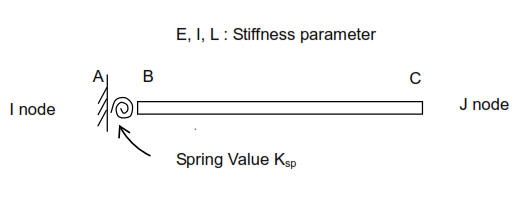
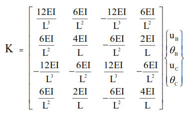
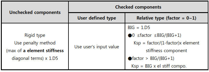
Enter the end release conditions (Hinge, Sliding, Roller Joint and Partial Fixity) at both ends of beam elements, or replace or remove previously entered end release conditions.
From the Main Menu select Boundary > Release/Offset > Beam End Release.
Click ![]() to the right of Beam End Release: Display the Beam End Release Table
to the right of Beam End Release: Display the Beam End Release Table
 Boundary Group Name
Select a Boundary Group in which the specified boundary condition is included. Select "Default" if Group assignment is unnecessary. Click ![]() to the right to prompt the "Define Boundary Group" dialog box to add, modify or delete Boundary Groups.
to the right to prompt the "Define Boundary Group" dialog box to add, modify or delete Boundary Groups.
|
The following buttons simplify the individual data entries described above:
![]()
To release the bending stiffness about the element's local y- and z-axes at both ends
![]()
To release the bending stiffness about the element's local y- and z-axes at N1 end
![]()
To release the bending stiffness about the element's local y- and z-axes at N2 end
![]()
To restore all the end release conditions at both ends to fixed conditions
![]() Revision of Civil 2014 (v2.1)
Revision of Civil 2014 (v2.1)


