Hydrostatic Pressure Loads
Enter the hydrostatic pressure (fluid potential) loads at the edges or faces of Plate, Plane Stress, Plane Strain or Solid Elements. The loads can be specified as linear loads or curved loads. Curved loads can be used for earth pressure (such as due to earthquakes) acting on underground structures.
The hydrostatic pressure loads are calculated at each corner node of the elements. The point pressure is obtained by multiplying the distance from the given surface of the fluid by the density of the fluid.
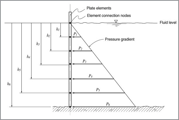
Pressure loads due to the fluid potential at the connection nodes of plate elements
From the Main Menu select Load > Static Load > Hydrostatic Pressure Loads.
|
Direction
Local x: Pressure loads applied in the element local x-direction
Local y: Pressure loads applied in the element local y-direction
Local z: Pressure loads applied in the element local z-direction
Global X: Pressure loads applied in GCS X-direction
Global Y: Pressure loads applied in GCS Y-direction
Global Z: Pressure loads applied in GCS Z-direction
Plane Strain: plane strain element
Axisymmetric: axisymmetric element
Pressure Edge: Refer to the figure to select the edge numbers to be loaded.
Solid: solid element 8 Nodes Solid
6 Nodes Solid
4 Nodes Solid
Pressure Face: Refer to the figure to select the face number to be loaded.
Direction
Normal: Pressure loads applied normally to the face of the solid elements
Global X: Pressure loads applied in GCS X-direction
Global Y: Pressure loads applied in GCS Y-direction
Global Z: Pressure loads applied in GCS Z-direction
Projection
When the pressure loads are applied to plate or solid elements in the direction of 'Global X, Y or Z', select whether or not to project the loads on a plane perpendicular to the loading direction.
Yes: project the pressure loads
No: the pressure loads are applied along the entire face
![]() Load Type is defined as Linear Loads
Load Type is defined as Linear Loads
 Loads
Loads
The application conditions for hydrostatic pressure loads are as follows:
Hydrostatic Pressure = P0 + g(H - h)
Where, H > h (position of the element connection nodes)
Gradient Direction: Assign the gradient direction of the hydraulic potential - increasing direction from the fluid surface
Global ( -X )
Global ( -Y )
Global ( -Z )
![]() Reference Level (H): Reference level for the pressure due to the hydraulic potential of fluids (enter with the mouse or keyboard)
Reference Level (H): Reference level for the pressure due to the hydraulic potential of fluids (enter with the mouse or keyboard)
Constant Intensity (P0): Pressure acting on the fluid surface
Gradient Intensity (g): Specific weight of fluid
Note
In order to apply lateral soil pressure onto a structure as Hydrostatic Pressure Loads, the following needs to be observed:
Element Type needs to the Plate type. The structure should be divided into small elements so that its flexural behavior is well reflected.
The Direction is defined as the direction of the acting loads. Gradient Direction is generally specified as the gravity direction (Global-Z).
Constant Intensity (Po) is entered to reflect the soil pressure due to overburden to which the soil pressure coefficient is applied. Gradient Intensity (g) is applied with the soil pressure coefficient and entered as follows depending on whether or not the level of ground water is considered.
1) When ground water level is not considered (only soil effect is entered)
Soil: g = soil pressure coefficient * unit weight of soil
2) When ground water level is considered (effects due to soil and ground water are separately entered)
Soil: g = soil pressure coefficient * unit weight of submerged soil
Ground water: g = unit weight of water
(For ground water, Reference level (H) is the ground water level.)
When the Curved Load Type is selected, the curvilinear distribution is given by
P(x)=ax^0.5+b
P(x)=ax^2+bx+c