Main Control Data
Enter the basic boundary conditions for elements and the analysis conditions for nonlinear elements.
By checking on "Consider Section Stiffness Scale Factor for Stress Calculation". section stiffness variation can be considered for stress calculation.
From the Main Menu select Analysis > Main Control > Main Control Data.
 Auto Rotational DOF Constraint for Truss/Plane Stress/Solid Elements
Automatically constrains the rotational DOF when elements without rotational DOF are used.
Auto Normal Rotation Constraint for Plane Elements
Automatically constrains the rotational DOF about the axis perpendicular to the plane of a plate element in order to remove unnecessary buckling modes that can occur in a plate element without out-of-plane rotational stiffness. This option is not applicable to a plate element with out-of-plane rotational stiffness.
Tension/Compression Truss Element (Elastic Link/Inelastic Spring)
|
|
If a truss element or a tension-only/compression-only elastic link element is used, the program automatically iterates the linear analysis, as shown in the left flow chart, to find a solution. The tension-only/compression-only elements that are applicable to this function are as follows: Compression-only/Tension-only Truss Element Compression-only/Tension-only Elastic Link Compression-only/Tension-only Point Spring Support Since the stiffness of the nonlinear members is influenced by the analysis result, the stiffness and the member forces should be determined by iterative analysis. The analysis result using the nonlinear members cannot be linearly combined with other load cases. When the combined result is required, the load combination using the nonlinear members should be applied as a single load case and the analysis should be performed independently. Create Load Cases using Load Combinations is used to create a new load case using the predefined load combination that was generated using several load cases. |
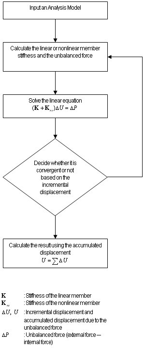
Number of Iterations/Load Case: Enter the maximum number of iterations used to determine the converged condition for each load case.
Convergence Tolerance: Enter the convergence tolerance.
Note
![]()
The degree of convergence of the result due to iterative nonlinear analysis is expressed in terms of displacement. If the Displacement error norm is less than the Convergence Tolerance, the analysis result is considered to be convergent.
Consider Section Stiffness Scale Factor for Stress Calculation
Use the section properties reflecting the scale factors, which were defined in Section Stiffness Scale Factor, for stress calculations. Default is checked off.
Note
Select whether or not to consider the increase or decrease in section stiffness for stress calculations. Even if the section stiffness changes, it is common to use the gross section for stress calculations. Thus, the default is checked off.
![]() Transfer Reactions of Slave Nodes to the Master Node
Transfer Reactions of Slave Nodes to the Master Node
Transfer reactions of Slave Nodes to the Master Node. Default is checked on.
Note
When this option is checked on, reactions of slave nodes are plotted as zero and total reactions including reactions of slave nodes are plotted in the Summation field of the Reactions Table. When this option is checked off, reactions of slave nodes are plotted in the reaction field of the corresponding slave node.
![]() Consider Reinforcement for Section Stiffness Calculation
Consider Reinforcement for Section Stiffness Calculation
Consider the reinforcement entered into a PSC section for section stiffness calculation. When this option is checked off, the reinforcement will not be considered for the section stiffness calculation. Default is Check Off.
For design, the reinforcement is considered for the section stiffness calculation regardless of whether the option is checked or not.
When shear steel bar is entered, the reinforcement is considered for the section stiffness calculation regardless of whether the option is checked or not. The stresses in PSC beam section defined with shear steel bar are produced as sig-xz (bar) in Beam Stresses (PSC).
![]() Change Local Axis of Tapered Section for Force/stress Calculation
Change Local Axis of Tapered Section for Force/stress Calculation
When the section offset of tapered section is specified as top or bottom of the section, the member forces and stresses can be obtained along with the local axis parallel to the offset line. This option is useful when the user wants to obtain the vertical forces parallel to the gravity direction in tapered section.
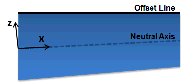
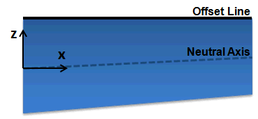
(a) when the option is checked off (b) when the option is checked on
Change Local Axis of Tapered Section for Force/stress Calculation option