Wave Loads
Generate wave load parameters for static/dynamic analysis.
From the Main Menu select Load > Settlement/Etc. > Etc. > Wave Loads.
![]() Enter new or additional wave load parameters.
Enter new or additional wave load parameters.
Click  .
.
![]() Modify previously entered wave load parameters.
Modify previously entered wave load parameters.
Select the relevant wave load parameter from the wave load list of the dialog box and click  .
.
![]() When deleting previously entered wave load parameters.
When deleting previously entered wave load parameters.
Select the relevant wave load parameter from the wave load list of the dialog box and click  .
.
![]() Display the defined wave load in graph format.
Display the defined wave load in graph format.
Click  .
.
![]() Display the defined wave load in the table format.
Display the defined wave load in the table format.
Click  .
.
 Generation Type
Static Load(Nodal Loads): Wave loads are automatically converted into static nodal loads. Different static load cases are generated by Critical Positions.
Time History Load: Wave loads are automatically converted into time history loads. In order to convert into time history loads, Time History Load Case must be defined in advance. Click [...] button to generate Time History Load Case.
General Parameters
Vertical Coordinate: Select the global axis of vertical direction of the wave load. Horizontal direction is always applied as Global X-axis.
Water Weight Density
Water Depth: Water depth based on the mean sea level (M.S.L)
Mudline Elevation: Vertical level of mud line with respect to the mean sea level (M.S.L)
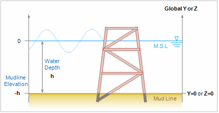
In the figure above, the left vertical axis is with respect to the mean sea level. The right vertical axis is with respect to the Mudline and will be used in the modeling. Wave loads are not applied to the elements located below mud line, or elements marked in gray in the figure above.
Wave Load Parameters
Drag & Inertia Coefficients
Type
Constant : Apply the identical drag coefficient regardless of section diameter.
Linear Interpolation : Apply the drag coefficient by section diameters. The program performs linear interpolation for the diameters not specified in the table.
Smooth/Rough
Drag & Inertia Coefficient
Drag Coefficient (Cd): Drag coefficient applied to the perpendicular direction of an element
Tangential Drag Coefficient (Cdt) : Drag coefficient applied to the tangential direction of an element
Inertia Coefficient (Cm): Inertia coefficient applied to the perpendicular direction of an element
Tangential Inertia Coefficient (Cmt): Inertia coefficient applied to the tangential direction of an element
Override Coefficients with Structure Group: Enter the drag and inertia coefficient by structure group.
Water Characteristics
Type
Airy Wave
Airy Wave (mean position)
Stokes V Wave
Stream Function w/ Current Effect
Stream Function w/o Current Effect
Cnoidal Wave
Solitary Wave
Function Order: Order of Stokes wave theory
Wave Direction: Wave load direction. Enter the degree from Global X-axis in counterclockwise direction.
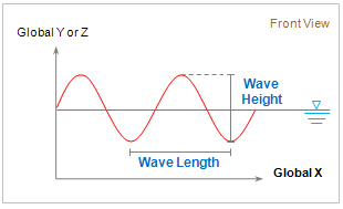
Wave Height
Wave Length
Wave Period
Kinematics Factor: Factor considering irregular behavior of wave load. 0 < Kinematics factor ≤ 1
Current Velocity
Surface(M.W.L): Velocity of current at the mean water level (M.W.L)
Bottom: Velocity of current at the bottom of sea
Validation Check of Specified Wave Theory: Validate the specified wave load data based on the wave theory.
Current Profile: Current loads will be generated by entering data in the Current Profile and will be included in the wave load cases. Note that these data will be neglected when "Stream Function with Current Effect" type is selected for the wave load type.
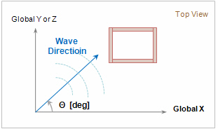
Direction : Refer to the figure below for wave direction.
Current Blockage Factor: Blockage factor of current due to structure
Elevation : 0 ≤ Elevation ≤ Depth of water(h)
Velocity : Velocity of current
Marine Growth: Define the elevation and thickness to consider the changes of thickness of structure due to attached organism.
Crest Position
Critical Position: Generate nodal loads which will cause one of the following items depending on the position of crest.
Maximum Moment at Bottom
Minimum Moment at Bottom
Maximum Shear at Bottom
Minimum Shear at Bottom
Maximum Force Upward
Maximum Force Downward
Initial Position : Initial length/degree/time of wave load
Increase Step : Increment of crest position
Number of Positions : Number of positions to be calculated