Cable Force Tuning
Many iterations are required in order to obtain the optimum cable pretensions for a cable-stayed bridge. Cable Force Tuning reduces the repetitive computation process. Cable Force Tuning calculates the effects of the cable pretension (or load factor) on the displacements/member forces/stresses through influence matrix and updates the results graph in real time.
One method of obtaining the optimum cable pretension is the Unknown Load Factor function using an optimization technique. Since Unknown Load Factor does not control the pretension directly, but finds the pretension that satisfies the given constraint conditions for displacement/member force/stress, the results may not be an engineering solution and fine tuning may be necessary
|
|
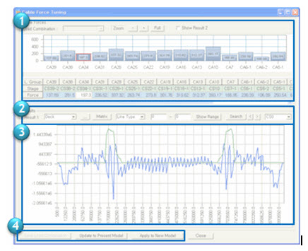
The process of Cable Force Tuning: 1. Adjust the cable pretension (or load factor) using the table or bar graph. 2. Select the result item for which the effects of the cable pretension are to be checked. 3. Produce the results graph for the result item selected from step 2. If the pretension (or load factor) is adjusted in step 1, it is reflected in the results graph in real time. 4. Save the adjusted pretension forces in a load combination or apply the new pretension forces to the cables directly using the pre-programmed buttons. |
From the Main Menu select Results > Bridge > Cable Control > Cable Force Tuning.
In order to calculate unknown load factors using optimization techniques, load combinations, load cases pertaining to the unknown load factors, specific constraints and object functions are required. All these data are collected in a unique and unknown load factor group for analysis. Several groups can be formulated where they can be saved, modified or deleted.
 Cable Forces
The cable pretension (or load factor) is displayed in the table and bar graph. The load factor can be entered from the table or can be adjusted by dragging the bar with the mouse or selecting the bar and using the keyboard (↑, ↓, Page Up, Page Down).
-
Model without construction stages
Load Combination: Select a load combination.
Zoom: When there are a large number of cables, expand the width of the table and bar graph. Click ![]() to view all the cable pretensions.
to view all the cable pretensions.
L.C.: The load cases that are included in the selected load combination.
Factor : The load factor for each load case that is part of the load combination is displayed. Get the preliminary load factors from the Unknown Load Factor function.
-
Model with construction stages
L.Group : Load Group
Stage : The construction stage when the corresponding Load Group is activated
Force : When a cable pretension or a load is applied to more than one element, an average pretension is displayed.
Results
Produces the updated graphs of the displacements/member forces/stresses for the adjusted pretension (or load). Select the result item for which the graph results are to be checked, from ![]() . The result item can be defined by clicking
. The result item can be defined by clicking ![]() .
.
Matrix : Display the influence matrix between the cable pretension (or load case) and the elements in the results group. The influence matrix is also displayed as an Influence Line in the graph so the influence of an individual tendon on the result can be directly visualized. In the figure below, the blue line shows the member forces and the green line represents the influence factors (the values highlighted as black in the Influence Matrix) for "CA13" cable pretension. The higher the value of the influence value the greater the influence of a change in pretension will be on the result for that specific part of the corresponding element. In this case these are the member forces that are highlighted as white.
The left hand figure shows the result before adjusting the "CA13" cable pretension. The right hand figure shows the result after the "CA13" cable pretension was increased. It can be observed that the result values which are highlighted as white have changed much while the other results have changed little.
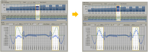
Pretension adjustment using Influence Line
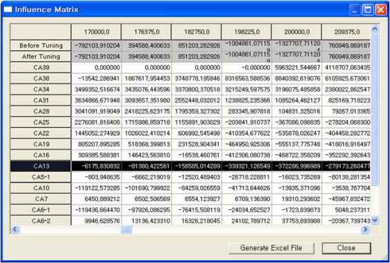
Influence Matrix dialog box
Graph type: Select among Line Type and Bar Type. The Bar Type is most convenient when displaying the axial forces of cables.
Show Range : The upper bound and lower bound that the user enters are displayed as a red line in the results graph.
Search : For the selected cables (CA34, CA31, CA28, CA25), cable tuning is automatically performed by increasing cable pretensions from the values entered in "from" to the values entered in "to" by the number entered in "Step".
Result Item:
Group : Select a Structure Group for which the results are to be produced.
Type : Select a result type (Truss Force, Beam Force, Displacement, Beam Stress).
x-Axis : Select an item for the x-Axis of the graph.
![]() : Add/modify the result item. When the entered name of the result item is different, a new item is added. When the entered name of the result item is identical, the previously entered data is modified.
: Add/modify the result item. When the entered name of the result item is different, a new item is added. When the entered name of the result item is identical, the previously entered data is modified.
![]() : Delete the selected result item.
: Delete the selected result item.
Save Results:
![]() : This option is valid only for a model without construction stages. The current load combination is updated with the adjusted load factors.
: This option is valid only for a model without construction stages. The current load combination is updated with the adjusted load factors.
![]() : The cable pretension loads are updated using the new factors or values obtained from the cable tuning process.
: The cable pretension loads are updated using the new factors or values obtained from the cable tuning process.
![]() : This option is valid only for a construction stage model. A new construction stage model is created with the adjusted pretensions.
: This option is valid only for a construction stage model. A new construction stage model is created with the adjusted pretensions.