General Camber Graph View
Camber diagrams are produced for the Structure Groups designated at the General Camber Control.
From the Main Menu select Results > Bridge > Camber/Reaction > General Camber > General Camber Graph View.
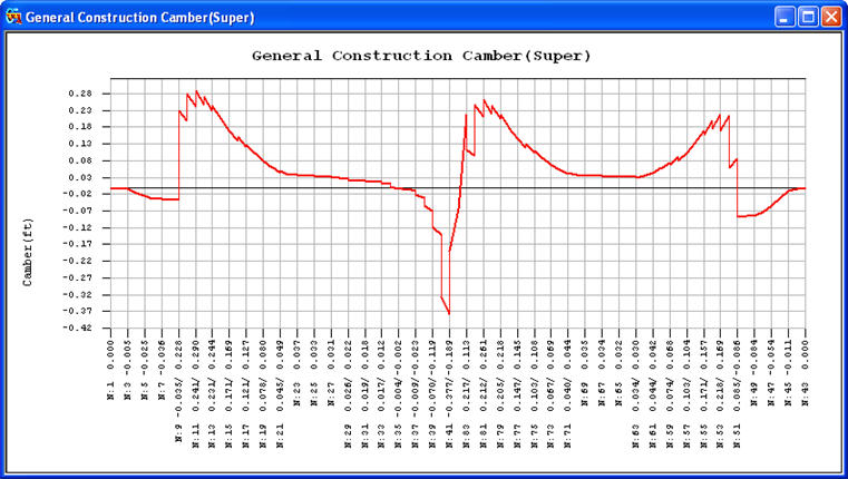
Construction camber diagram
The X-axis of the graph represents the locations of nodes of the bridge in question, and the Y-axis represents the magnitudes of cambers at the corresponding nodes. Two numerical values are noted directly above the node numbers. The top values are the cambers required at the time of installing the formwork, and the lower values are the subsequent displacements that will ensue after pouring concrete and dismantling the formwork. Once the above conditions are satisfied, displacements are increased due to additional loads applied during the construction stages, and upon completion of construction, all the displacements at the main girders become '0' and the superstructure becomes horizontally leveled.
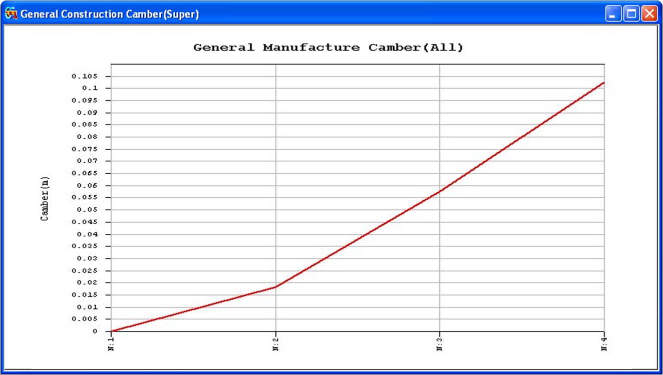
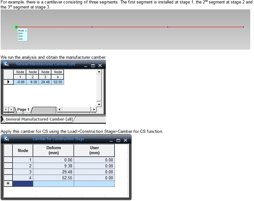
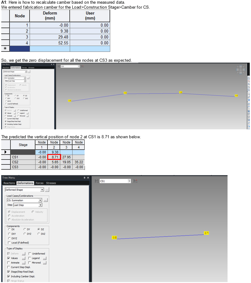
Fabrication camber diagram
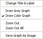
Right-click on the General Camber Graph screen to prompt the following Context Menu:
|
|
Change Title & Label
|
Note
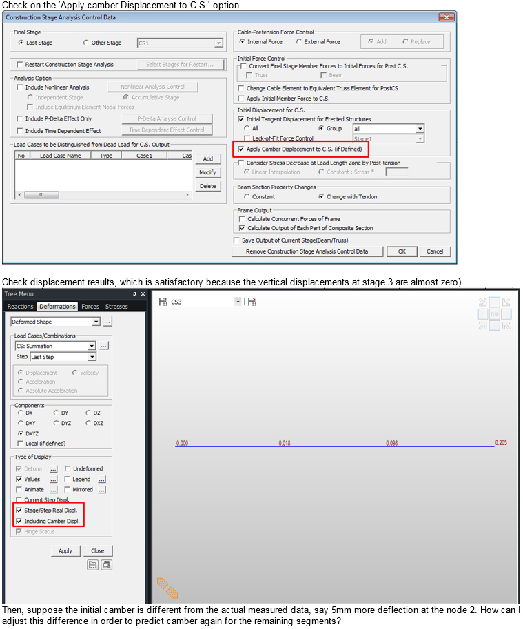
Select Initial Tangent Displacement for Erected Structures in Analysis > Construction Stage Analysis Control Data to produce a fabrication camber diagram.
![]() Revision of Civil 2015 (v1.1)
Revision of Civil 2015 (v1.1)
