Grillage Model Wizard (Layout)
The wizard automatically generates grillage model with the longitudinal members coincident with longitudinal webs for multicellular bridge decks. Define the road alignment information, the span information, and the boundary conditions etc in the Layout tab.
From the Main Menu select Structure > Wizard > Grillage Model Wizard > Layout
![]() Bridge Material
Bridge Material
Select the Material property of the bridge. The material should be defined in advance. Click ![]() to define a new material.
to define a new material.
![]() Span Information
Span Information
Specify the spans sequentially. Example - 300, 400, 2@300, 100
![]() Skew Angle
Skew Angle
Skew angle of the bridge in plan (θ deg)
 (+) indicates counter-clockwise direction.
Click ![]() to enter different skew angles by spans.
to enter different skew angles by spans.
![]() Offset
Offset
Distance between the reference line and the center line of the bridge
![]() Alignment of Transverse Members
Alignment of Transverse Members
Transverse members may be orthogonal or skewed with respect to the longitudinal members.
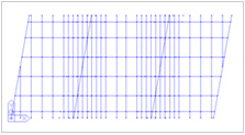
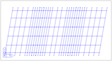
Perpendicular Skewed
![]() Radius
Radius
Specify the radius in the case of a horizontally curved bridge.
Convex: Convex curvature (center of circle located below)
Concave: Concave curvature (center of circle located above)
Multi-Curve: Click ![]() to input multi-curves
to input multi-curves
The curvature can be defined as the combination of a straight line and a curve.
![]() Boundary
Boundary
-
Integral Type
In case of the integral bridge, enter data for the substructure as follows.
Abutment Section
Abutment Height
Pier Section
Pier Height
Bottom of Abutment / Pier: Boundary conditions of substructure
Fixed: Set as a fixed support.
Spring Support: Set as a spring support. Specify the horizontal and vertical spring stiffness. Click ![]() if spring stiffness is different for each support.
if spring stiffness is different for each support.
-
Bearing Type
When superstructure and substructure are connected with bearings:
Supports: Bearings are represented by fixed / free support. Once the position of fixed support is determined, all the other supports are considered as free support longitudinally.
Elastic Link: Bearings are represented by Elastic Link. Enter the stiffness of bearings by directions for the abutments and the piers. Click ![]() to enter different stiffness for different supports.
to enter different stiffness for different supports.
Fixed Support: Select longitudinally fixed support. Longitudinally and transversely fixed bearing is used as a reference point for the determination of the direction of free bearings in the In Line with Fixed Support option.
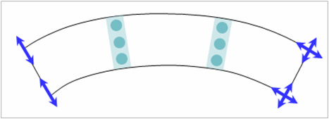
Direction: Choose the method of determining direction of the free bearings.
Tangential: The restraint-free direction is tangent to the longitudinal axis of the bridge. (i.e. tangent to the curvature of a curved bridge or in the direction of a straight bridge)
In line with Fixed Support: The restraints are freed in the directions from the individual supports to the fixed support.

Tangential in Line with Fixed Support
-
Hybrid Type
When the piers are integral with the deck structure but the abutments are not integral with the deck structure:
Abut: Bearing
Supports: Bearings are represented by fixed / free support. Support conditions are automatically considered as shown below. Longitudinal movement for the start abutment is fixed. All the other supports are considered as free support both longitudinally and transversely.
Elastic Link: Bearings are represented by Elastic Link. Enter the stiffness of bearings by directions for the abutments. Click ![]() to enter different stiffness for different abutments.
to enter different stiffness for different abutments.
Pier: Integral
Pier Section
Pier Height
Bottom of Pier: Boundary conditions of piers
Fixed: Set as a fixed support.
Spring Support: Set as a spring support. Specify the horizontal and vertical spring stiffness. Click ![]() if spring stiffness is different for each pier.
if spring stiffness is different for each pier.
![]() Open...
Open...
Open the data saved as in the *.wzd file type in the Grillage Model Wizard. By using this function, we can re-execute midas Civil and subsequently check and modify the previously entered data within the Wizard.
![]() Save As...
Save As...
Save the data entered in the Grillage Model Wizard as the *.wzd file type.