MSS Bridge
The Wizard automatically generates the model data of a PSC box bridge constructed by an MSS, Movable Scaffolding System, by entering simple variables. The data include elements, boundary conditions, tendon placement, construction stages, etc. for a bridge composed of PSC (prestressed or post-tensioned Concrete) Box sections.
Note 1
The input data in MSS Bridge Wizard are saved in the corresponding dialog boxes once the Wizard is executed normally. We can recall the input data after closing the Wizard and subsequently check, modify and re-execute the Wizard. In addition, Wizard data can be saved as a file with .wzd extension, which can be recalled even after closing the program.
Note 2
A "Two Cell" type section can be defined, which as a 2 cell PSC (prestressed or post-tensioned concrete) Box section. Moreover, the section at supports can be defined separately from the Diaphragm of the Section tab.
Note 3
MSS (Movable Scaffolding System) and traditionally shored FSM (Full Staging Method) are separated from the previously combined wizard.
From the Main Menu select Structure > Wizard > MSS Bridge
![]() Bridge Model Data Type
Bridge Model Data Type
Select a Data Input Type.
Type 1: Define PSC Box Section and tendon layout in conformity with the form provided by the Wizard.
Type 2: Recall the PSC Box Section and tendon layout that has been defined by the user manually.
When Type 2 is selected, the user can define multi-Cell Section and straight and curved tendon layout.
![]() Model tab
Model tab
Enter the material properties, configuration and staging information of a bridge.
Bridge Material
Define the material type of the bridge girder. Click the ![]() to the right of the selection field to add or modify material data..
to the right of the selection field to add or modify material data..
Span (L): Specify the spans consecutively.
Radius: Specify the radius in the case of a curved bridge.
Convex: Convex curvature bulging to the +ve direction of the Global Y-axis on Global X-Y plane
Concave: Concave curvature bulging to the -ve direction of the Global Y-axis on Global X-Y plane
Fixed Support: Location of the fixed support (If more than one fixed support exists, the general procedure is used to revise the Wizard-generated data)
Segment Division per Span: Number of elements per span
Cold Joint (S3): Location of concrete construction joint
Anchorage (S4): Location of tendon anchorage from the construction joint. The distance applies symmetrically to the construction joint and represents the ends of the thickened webs.
Diaphragm (S5): Distance from the center of a pier to one end of the diaphragm. The distance applies symmetrically and defines the zone of thickened webs.
Stage duration: Duration of each construction stage (ex., Duration for constructing the bridge segment from the buttress to the construction joint in the above diagram). It represents the time that takes to assemble, cast and cure the segment and dismantle the formwork.
Initial Member Age: for member (girder)
Specify the initial age, which is the maturity of concrete at the start of a construction stage (i.e., aging of concrete taken place in the immediately preceding stage). It represents the age of concrete when the elements become subjected to loads. The member age is used to reflect the compressive strength (modulus of elasticity), creep, shrinkage, tension loss in tendons, etc. The age is applied at the time of calculating the reaction due to the self-weight of concrete and at the time the reactions of the MSS girders are imposed.
Movable Scaffolding Reaction
When MSS is selected as the Bridge Type, the rear cross beam that supports the movable scaffolding girders for the subsequent stage is located at 3m back from the construction joint of the immediately preceding segment, which in turn supports the rear cross beam. The movable scaffolding girders are supported by the rear cross beam and the next pier. The user enters the reaction at the rear crossbeam due to the weight of the movable scaffolding as it varies from supplier to supplier. The program automatically calculates the weight of concrete and applies to the corresponding construction stage.
Note
MSS/FSM Wizard automatically generates Element groups, Boundary groups and Load groups to create a bridge model. Refer to Define Structure Group, Define Boundary Group, and Define Load Group.
![]() Section tab - Type 1
Section tab - Type 1
Define the PSC (prestressed/post-tensioned concrete) Box section by entering the appropriate dimensions.
Section Type
1 Cell
2 Cell
Center: Mid-span section
Joint: Section at the construction joint
Diaphragm
![]() H1, H2, H3, ..., H10, B1, B2, ..., B10, T
H1, H2, H3, ..., H10, B1, B2, ..., B10, T
Referring to the guide diagram, enter the required dimensions.
![]() View Option
View Option
Bitmap
The dimension guide diagram is displayed in the dialog box.
Drawing
Using the dimensions, the section is displayed in the dialog box to a true scale.
![]()
If Drawing is selected, the section is regenerated to reflect the revised dimensions.
![]() Section tab - Type 2
Section tab - Type 2
When Type 2 is selected, this tab allows the user to define Sections for Center, Joint and Diaphragm by importing previously defined Sections. When Type 1 is selected, 1 Cell and 2 Cell Sections can be defined. When Type 2 is selected, multi-Cell Sections can be defined.
![]() User Define
User Define
Center : Select a Section previously defined by the user for Center. If a Section has not been defined, click ![]() to define a Section.
to define a Section.
Joint : Select a Section previously defined by the user for Joint.
Diaphragm : Select a Section previously defined by the user for Diaphragm.
![]() Update Display
Update Display
Display the updated Section configuration.
Note
In MSS method, Tapered Section cannot be defined and the Section must have the same configuration.
)
![]() Tendon tab - Type 1
Tendon tab - Type 1
Enter the positions and spacings of the web tendons.
![]() N, G1, G2, ..., S1, S2, ..., C, a1, a2
N, G1, G2, ..., S1, S2, ..., C, a1, a2
Referring to the guide diagram, enter the number and the positions of the tendons.
![]() Tendon Property
Tendon Property
Specify the type of tendons. Click the ![]() to the right of the selection field to prompt the "Tendon Property" dialog box to add or modify tendon properties.
to the right of the selection field to prompt the "Tendon Property" dialog box to add or modify tendon properties.
![]() Jacking Stress
Jacking Stress
Specify the tensioning stress for the tendons.
Su: Ultimate tensile strength
Sy: Yield strength
![]() Grouting
Grouting
Specify the timing of grouting tendons. Once the ducts are grouted, the transformed section properties are subsequently considered. The input signifies the timing of incorporating the transformed properties.
Prestressing step
Grouting takes place at the time of tensioning the tendons.
Every n Stage
Grouting takes place at every n stages. If n=1is entered, the grouting is assumed to take place at the next stage after the corresponding tendons are stressed. If n=2 is entered, the grouting is assumed to take place at the third stage after the two corresponding segments have been stressed.
![]() a, b, c
a, b, c
Referring to the guide diagram, enter the dimensions for defining the tendon.
![]()
![]()
Open the data saved as an *.wzd file type in the MSS Bridge Wizard. By using this function, we can re-execute midas Civil and subsequently check and modify the previously entered data within the Wizard.
![]()
![]()
Save the data entered in the MSS Bridge Wizard as an *.wzd file type.
![]() Tendon tab -Type 2
Tendon tab -Type 2
Define the layout of straight or curved tendons by entering the distances from the top and bottom of the girder, the angle of inclination of the tendon and the radius of curvature at an inflection point.
![]() N, C1~C4, G1~G6, S1,~S2, R1~R5, Theta1~Theta3
N, C1~C4, G1~G6, S1,~S2, R1~R5, Theta1~Theta3
Referring to the guide diagram, enter the number of tendons and the dimensions required to define the tendon layout.
![]() Tendon Property
Tendon Property
Specify the type of tendons. Click the ![]() to the right of the selection field to prompt the "Tendon Property" dialog box to add or modify tendon properties.
to the right of the selection field to prompt the "Tendon Property" dialog box to add or modify tendon properties.
![]() Jacking Stress
Jacking Stress
Specify the tensioning stress for the tendons.
Su: Ultimate tensile strength of tendons
Sy: Yield strength of tendons
![]() Grouting
Grouting
Once the ducts are grouted, the transformed section properties of tendon and grouting are subsequently considered. The input signifies the timing of incorporating the transformed properties or the timing of grouting tendons.
Prestressing step
Grouting takes place at the time of tensioning the tendons.
Every n Stage
Grouting takes place at every n stages. If n=1is entered, the grouting is assumed to take place at the next stage after the corresponding tendons are stressed. If n=2 is entered, the grouting is assumed to take place at the third stage after the two corresponding segments have been stressed.
Number of Cells
Number of Cells of PSC Box Section defined in Section tab
Symmetric
Select this option when the web tendons at each side are symmetrical.
Eyi
Enter the horizontal distance from the center of the section to the center of the web.
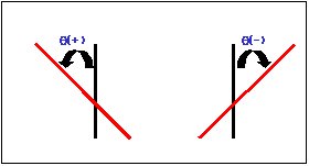
θi
Enter the angle of inclination of the web tendons. The sign convention is illustrated in the figure below.
ai
Enter the horizontal distance from the web center to the tendon. The left of the web center is taken as negative and the right is taken as positive.
![]()
![]()
Open the data saved as a *.wzd file type in the MSS Bridge Wizard. By using this function, we can re-execute midas Civil and subsequently check and modify the previously entered data within the Wizard.
![]()
![]()
Save the data entered in the MSS Bridge Wizard as an *.wzd file type.