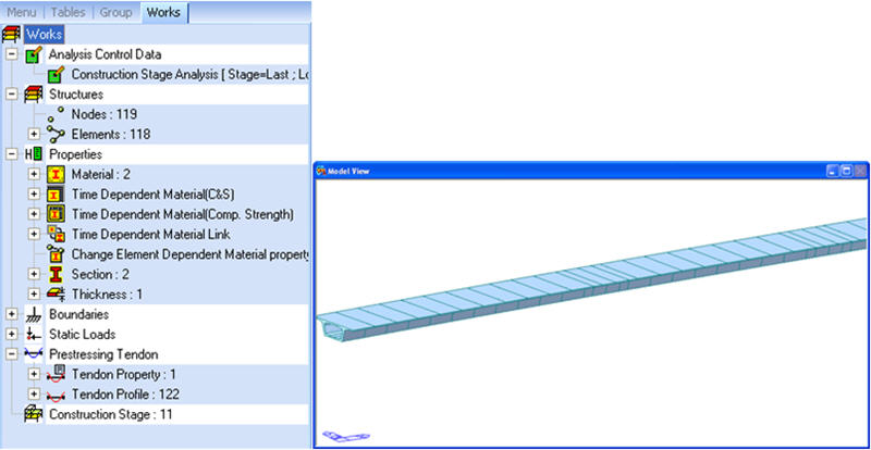
Section & Reinforcement
Assign the section variation and reinforcement information along the primary direction.
Definition of section variation: Upon investigating the sections of FCM or FSM bridges, the user can observe that the PSC Box section does not change uniformly, but generally each section part varies differently. For example, consider a case where the thickness of the top flange is constant, bottom flange varies according to a 2nd order equation, and the web varies linearly. In this case, there is a limit for the Tapered Section Group function to model this type of bridge, and the user should modify the model after this function is applied. However, by using the Section & Reinforcement function, the user can define the variation in each section by parts and, thus, a more detailed model can be generated.
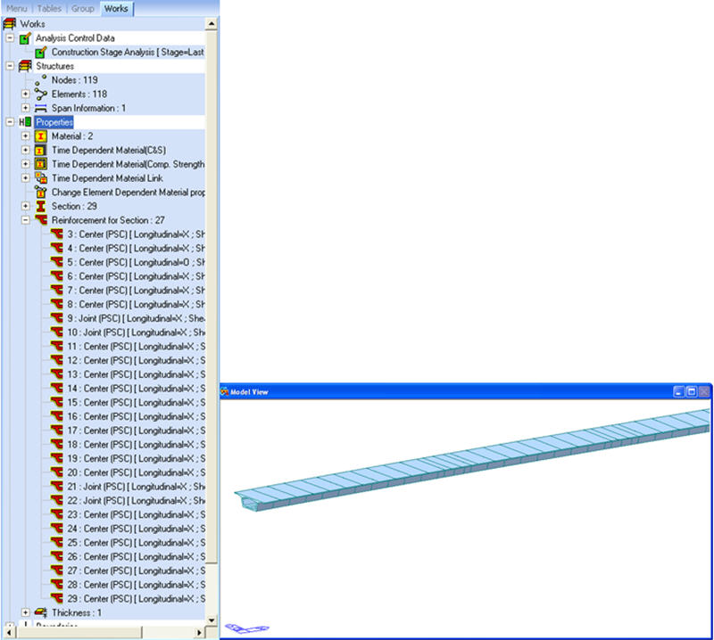
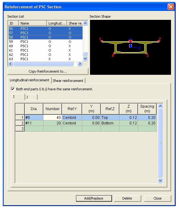
Assigning Reinforcement information: By using the Reinforcement of PSC Section function that has been incorporated in midas Civil version 7.0.1, the user can input the reinforcement information (transverse, shear and torsion) for a PSC Type Section. Since this method inputs the reinforcement information by each section, it is not applicable for PSC Box bridges in which the reinforcement varies along the primary direction. Therefore, to model the variation of reinforcement along the primary direction by using this function, there is a slight inconvenience in subdividing the elements into parts and then defining the reinforcement in each section. However, by using the Section & Reinforcement function and inputting the reinforcement information along the primary direction, the program automatically divides the elements and defines the sections for the user. This will minimize the time required for a generating a particular model.
After inputting the section variation and reinforcement information, and then executing the Wizard, the element divides automatically, generates tapered sections, and inputs the reinforcement information for each section.
Applicable sections: 1CELL, 2CELL, nCELL, nCELL2, Tee, and CMPWEB of PSC sections are applicable. Non-symmetrical sections are not applicable, except the Tee section.
From the Main Menu select Structure > Wizard > PSC Bridge >Section & Reinforcement
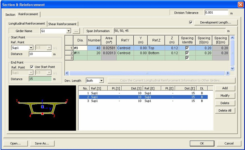
Division Tolerance
The program automatically divides the element with respect to the variation in section dimensions and the input of reinforcement information. If the distance between the new automatically generated node and the existing node is less than 0.001m then the program uses the existing node. This stops the program to generate too many fine elements caused by auto generation.
![]() Section tab
Section tab
Defines the variation of section dimensions through the primary direction of the bridge.
Girder Name
Select the girder to define variation of section dimension from the predefined girder list of Span Information. If no girders are defined then click on [..] button and define a new girder.
Typical Section
Select the typical section to use for defining the variation of section dimension
Span Information
Displays the Span Information of the selected girder.
![]() : Copies the current section information to other girders.
: Copies the current section information to other girders.
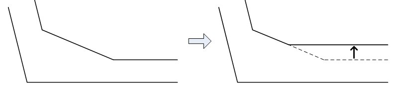
![]() Variation of Height
Variation of Height
The height variation is defined as the change of length of the web, and the angle of the web and haunch does not change. But exceptionally for Tee sections, when the height changes the thickness of the bottom of the web does not change.
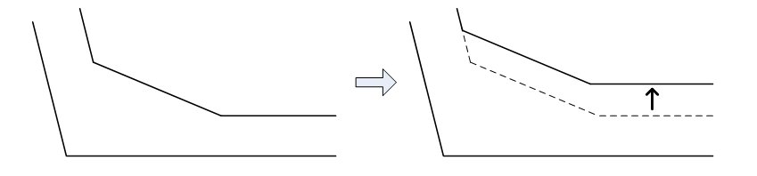
![]() Variation of Width
Variation of Width
Reflects the variation of width due to the location change of the top and bottom flange. The angle of the bottom of the flange changes.
![]() Variation of flange thickness
Variation of flange thickness
The thickness of the flange is based on the center part of the inner side of the box and the thickness of the inner side flange will change.
![]() Variation of web thickness
Variation of web thickness
Web thickness is the thickness of the normal direction of the web. For External Web the inner side of the web changes and for Internal Web both side of the web changes.
![]() When selecting Height Tab/Width Tab/External Web Thk. Tab/Internal Web Thk. Tab
When selecting Height Tab/Width Tab/External Web Thk. Tab/Internal Web Thk. Tab
Ref. Line
Base line from where the inputted distance is measured. The section varies at the inputted distance from this base line. Any node location can be selected as a Ref. Line.
Distance
Distance from the Ref. Line. (+,-)
Dimension
Enter the dimension for the current section.
Curve Type
Enter the curve type that applies to the curve from the current location to the next location. (line or curve)
Exp.
Input the order of the curve, if Curve is selected from the Curve Type.
Sym. Plane Distance
Input the axis of symmetry if Curve is selected from Curve Type.
![]() When selecting Top Flange Thk. Tab/Bottom Flange Thk. Tab.
When selecting Top Flange Thk. Tab/Bottom Flange Thk. Tab.
Haunch Intervention
Assign the relation of haunch to the thickness change of top and bottom flange.
When this option is selected top of the bottom flange (or bottom of the top flange) subtracts the haunch to increase the thickness.
When this option is not selected the haunch remains the same during thickness change.
Other options follow the previous tab.
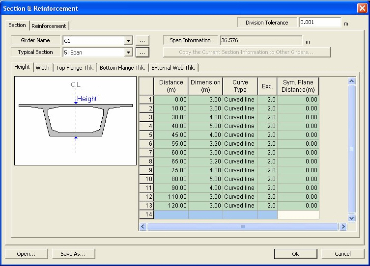
[Example] This is an example applying a variation of sections through the primary direction.
![]() Reinforcement tab
Reinforcement tab
Input the reinforcement information through the primary direction.
Girder Name
Select the girder to define the information of reinforcement from the predefined girder list of Span Information. If no girders are defined then click on [..] button and define a new girder.
![]() When Longitudinal Reinforcement Tab is selected
When Longitudinal Reinforcement Tab is selected
Starting Point: Enter the starting point of the reinforcement.
Ref. Point: Enter the Ref. Point to define the starting point of the reinforcement. Ref. Point can be entered as the support or any tenth of the span (0.1L, 0.2L, etc.).
Distance: Enter the distance from the defined Ref. Point. The reinforcement starts from this point. Negative values can also be inputted.
Reinforcement is entered 10 m from the starting point.
Reinforcement is entered 10 m from 0.2L of the second span.
End Point: Enter the end point of the reinforcement.
Ref. Point: Enter the Ref. Point to define the end point of reinforcement. Ref. Point can be entered as the support or any tenth of the span (0.1L, 0.2L, etc.). If the box is checked on, then the Ref. Point defined from the Starting Point is used.
Distance: Enter the distance from the defined Ref. Point. The reinforcement ends at this point. Negative values can also be inputted.
Dia.: Enter the diameter of the rebar.
Number: Enter the number of the rebar
Area: Enter the cross-sectional area of the total reinforcement.
Ref.Y
Assign a standard point in the section to input the transverse direction of the reinforcement. Centroid locates the centroid of the rebar to the center of the section and Left locates the rebar from the left side of the section.
Y : The transverse direction distance from the standard point (Ref. Y) to the centroid of the primary direction rebar.
Ref.Z : Assign a standard point in the section to input the perpendicular direction of the reinforcement. Select either Top (Top of the section) or Bottom(Bottom of the section).
Z : The perpendicular direction distance from the standard point (Ref. Z) to the centroid of the primary direction rebar. If TOP is selected then from the top of the section towards the rebar is the positive direction. And vise versa if BOT is selected.
Spacing Identity: Checking this option the rebar spacing of the starting point and end point the defined interval (Start to End) will be inputted identically.
Spacing [S]: The rebar spacing of the starting point of the defined interval.
Spacing [E]: The rebar spacing of the ending point of the defined interval.
![]() : Define the rebar length with Development Length considered.
: Define the rebar length with Development Length considered.
|
Enter the actual starting and end points of reinforcement. The Development Length is deducted from the entered rebar length. Enter the Development Length by rebar diameters and apply the Factors. The rebar length to be used in the analysis is "Entered Rebar Length - (Factor× FDL). Development Lengths can be applied to Top fiber and Bottom fiber differently. When "Top" is selected from Ref. Z and Z is entered, the Development Length for top fiber (Top tab) applies. Likewise, when "Bottom" is selected from Ref. Z and Z is entered, the Development Length for bottom fiber (Bottom tab) applies. Factor: Enter the factor to calculate the rebar length. The factor ranges from 0 to 1. FDL: Full development length The FDL (full development length) is based on the diameter of the rebar and the rebar length is calculated as follows: Length = Factor x FDL (Full Development Length) |
Dev. Length: Enter the location to apply the development length.
Both: Move both the starting and end points by a distance equal to the development length.
Start: Move the starting point by a distance equal to the development length.
End: Move the end point by a distance equal to the development length.
![]() When Shear Reinforcement. Tab is selected
When Shear Reinforcement. Tab is selected
Diagonal Reinforcement
Selected when Diagonal reinforcement is involved in design.
Pitch: Enter the spacing of diagonal rebar.
Angle: Enter the angle of diagonal rebar.
Aw: Enter the total area of diagonal reinforcement in the entire web.
Steel Bar for Web
This option is checked when calculating diagonal tensile stress due to shear steel bar.
Pitch: Enter the spacing of shear steel bar.
Angle: Enter the angle of shear steel bar.
Ap : Enter the total area of shear steel bar in the entire web.
Pe : Enter the effective tensile stress induced to the shear steel bar in the entire web.
Shear Reduction Factor: Enter the shear reduction factor.
Torsion Reinforcement
Selected when Torsional reinforcement is involved in design.
Pitch : Enter the spacing of transverse torsional reinforcement.
Awt : Enter the angle of transverse torsional reinforcement.
Alt : Enter the area of torsional reinforcement in the primary direction.
Enclosing Stirrup for Enclosed Section Area
Input the data needed to calculate the enclosed section area used for the calculation of torsional moment.
Cover Thickness : Input the cover thickness of the enclosed stirrup.
Include Flange/Cantilever : I-type section flange and cantilever part of Box type section is included in the enclosed section.
Note 1
If the data for enclosed stirrup is not entered, for Box type section the program inputs ½ of the web as the cover, and for T type section the program assumes the cover as zero and calculates the enclosed area.
Note 2
For the information of the reinforcement inputted can be checked at Properties>Section>Section Manager