Prestressed Composite Bridge Wizard (Load)
Define dead loads and live loads of the bridge
From the Main Menu select Structure > Wizard > Prestressed Composite Bridge Wizard > Load
![]() Pavement and Barrier
Pavement and Barrier
Refer to the following diagram for b1, b2, b3, b4, b4 & b5.
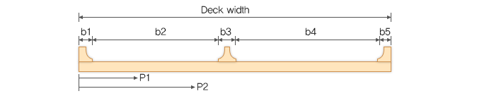
b1: Left barrier width, b5: Right barrier width. The barrier load is applied over the barrier width
b3: Median strip width. The median strip load is applied over the median strip width
b2, b4: Carriage way width. The wearing surface load is applied over the carriage way width
P1, P2: First and the second positions of additional load and utilities load, respectively
![]() Dead Loads
Dead Loads
When each loads are checked off, the program does not generate the data for the load case.
Equally to All Girder
DC(Before Composite): DC load case before the composite action will be distributed equally to all girders.
DC(After Composite): DC load case after the composite action will be distributed equally to all girders.
DW(Before Composite): DW load case before the composite action will be distributed equally to all girders.
Applying to 'Equally to All Girder'
Before Composite
Self Weight: Self weight
Wet Con'c: Weight of wet concrete. Load is generated on the concrete weight density and deck thickness
Form Work: Weight of form works
The Wet concrete and Form work loads should be input with the unit of force per length square. For Wet concrete, Weight density multiply by thickness makes force per length square
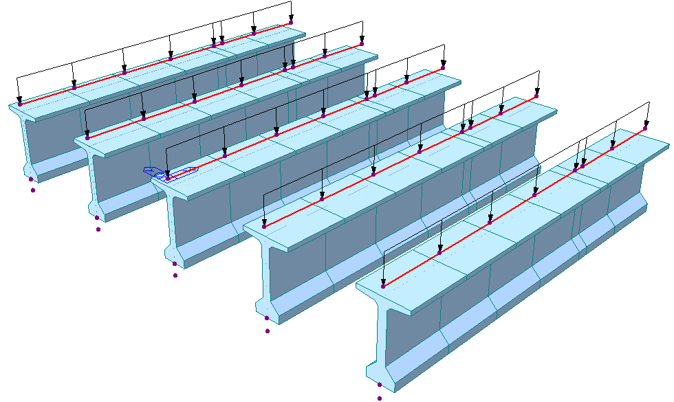
All frame modeling type: The load value is calculated with each deck width and applied to the each girder as an element beam load
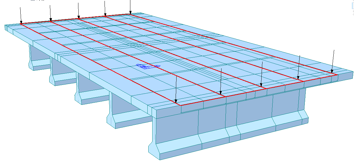
Deck as Plate modeling type: The load value is applied as a pressure load
S.I.P forms: Click to apply S.I.P forms instead of normal formwork. S.I.P forms will be applied as loading and it will remain in the place after the wet concrete is hardened.
-
Wet concrete load Case
After Composite
Barrier: Weight of the lane barrier
Median Strip: Weight of the median barrier/strip installed to separate the traffic lanes.
The Barrier, Median Strip magnitudes should be entered in the unit of force per linear length.
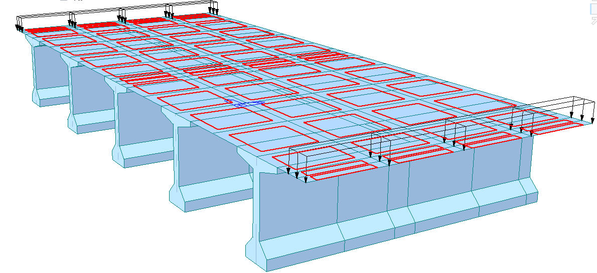
All frame modeling type: This load value is applied over the entire bridge length at the deck ends as nodal loads.
Deck as Plate modeling type: This load value is applied as pressure loads.
-
Barrier load Case
All frame type Deck as plate type
Additional Load: Weight of the additional point load. Position is defined by value entered. Use above diagram as a reference.
Basically, the distance (P1) is the distance from the reference axis to the first additional load. Multiple locations can be entered and separated by commas. The distance to each location is measured from the left end of the bridge cross section.
Additional load magnitudes should be entered in the unit of force per linear length.
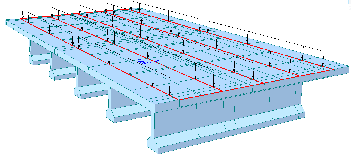
This load value is applied over the entire bridge length at the deck ends as nodal loads.
Wearing Surface: Weight of the wearing surface (e.g. asphalt) covering the bridge road
The load magnitude should be entered in the unit of force per length square. (Weight density multiply by wearing thickness)
All frame modeling type: This load value is calculated with each dummy deck spacing distance and applied to the each transverse deck as an element beam load
Deck as Plate modeling type: The load value is applied as a pressure load
-
Wearing Surface

All frame type Deck as plate type
Utilities: Weight of the utility point load. Position is defined by the value entered. Use the above diagram as a reference.
Basically, the distance (P2) is the distance from the reference axis to the first Utilities load. Multiple locations can be entered and separated by commas. The distance to each location is measured from the left end of the bridge cross section.
The Utilities load magnitude should be entered in the unit of force per linear length.
This load value is applied over the entire bridge length at the deck ends as nodal loads.
![]() Live Loads
Live Loads
Check on to define Live Loads
Define Moving Load Case 
Select moving load code to be used in analysis
Define Traffic Line Lane 
No. of Lanes: Number of lanes on the bridge. Use the diagram and the table (No. vs. Distance) to define the lane locations.
The distance to each lane center is measured from the left end of the bridge cross section.
Each lane width is automatically defined based on the moving load code selected before entering this “Define Traffic Lane”. Based on the Moving Load Code and Traffic Lane information, the program automatically creates the vehicle lane data.
Define Vehicles 
To enter new or additional vehicle loads
Vehicle loads can be either selected from the standard or manually defined as the “user-defined” type.