Prestressed Composite Bridge Wizard (Section)
Define the property, type, location and alignment of the girders and diaphragms.
The girder and diaphragm input options are different for the different girder types – precast girder type vs. spliced girder type. (The girder type – precast or spliced – is defined in the Layout tab.)
From the Main Menu select Structure > Wizard > Prestressed Composite Bridge Wizard > Section
![]() Deck Thickness
Deck Thickness
Specify the deck thickness.
For the All Frame type (refer to the Layout – Girder Type), this value is used for the section thickness of transverse dummy section.
For Deck as plate modeling approaches, this value is used as thickness of plate elements for deck modeling approaches.
![]() Haunch
Height
(Deck as plate, Girder as frame type only)
Haunch
Height
(Deck as plate, Girder as frame type only)
Specify the distance between the deck and the girders, the gap is connected by rigid links, and the longitudinal spaces are determined by the size of the plate element. If the haunch is zero, no gap is created between the deck and girder. If the haunch is not zero, gap is created accordingly with rigid links linking the gap.
![]() No. of Girders
No. of Girders
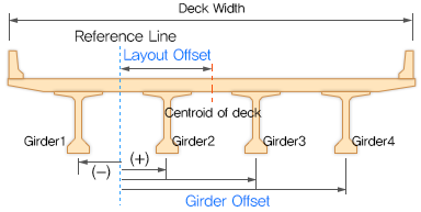
The offset to each girder center is input in the table.
![]() Girder Offset
Girder Offset
Distance between the reference line and the center line of each girder
The offset is negative when the offset is on the left side of the reference line in the longitudinal direction; the offset is positive when the offset is on the right side of the reference line in the longitudinal direction.
![]() Material
Material
Deck
Select the material property to be used in a deck element.
When the All Frame type is used, the selfweight of the deck is included. Also, based on the deck material selected, the wizard newly creates an additional material with the same properties as the deck but with zero weight density. For the All Frame type, like a Grillage modeling approach, transverse dummy beams are required for the transverse stiffness of the deck.
Girder
Select the material property to be used for the girder element.
Diaphragm
Select the material property to be used for the diaphragm.
Click
 to
define a new material or modify an existing material.
to
define a new material or modify an existing material.
![]() Transverse
Deck Element (All frame element type only)
Transverse
Deck Element (All frame element type only)
A rectangular section (Name: GirderWizRectangle_n) for the dummy deck are automatically generated based on the Deck Thickness & the Transverse Deck elements spacing length.
Spacing: Select one of the following options to define the spacing of the Transverse Deck Elements
Distance: Enter the distance to be used for the spacing of transverse deck element.
Divisions: Instead of spacing, the number of divisions can be used to locate the transverse deck elements.
Divisions per Span: Determine the number of division for each span. (e.g. “3@5” or “5,6,5” for a three-span bridge)
Angle type: Select one of the following options to define the skew type of the transverse deck elements.
Skew: The transverse deck elements is placed with the (support) skew angle which is defined in the Layout Tab.
Perpendicular: The transverse deck elements are perpendicular to reference line.
![]() Mesh size (Deck as Plate types only)
Mesh size (Deck as Plate types only)
Specify the size of the plate element for the deck.
Size of Plate Element
Specify the size of plate element for deck, web and flange.
![]() Diaphragm
Information
Diaphragm
Information
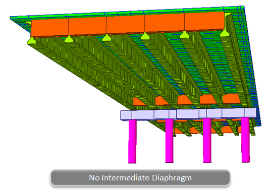
Diaphragms stabilize the main girders and contributes in the load distribution. For the splice girder type, diaphragms are typically installed between girders at the splice locations.
Diaphragm is modeled as a single beam type
Define Diaphragm Section
Define the section (s) to be used for each Diaphragm section. And diaphragm skew angle follows the skew angle that is defined the layout tab
Intermediate Spacing:
Select one of the following options to define intermediate support diaphragm locations. Distances / Division per span (Precast Girder Type only), Distances / Division per splice (Splice Girder Type only)
Distances / Divisions
The intermediate diaphragm locations can be input with the spacing distance length (Distance), the number of division per span (Division per span). This distance and division information is applied for the each span girder length.
Distances / Division per splice
The intermediate diaphragm locations can be input with the spacing distance length (Distance), the number of divisions per splice (Division per splice).

Adv...: Advanced Diaphragm.
Individual diaphragms can be included/excluded in the modeling of prestressed composite girder bridge.
End Support: End diaphragm located at the girder end at the abutment.
Pier Support: Pier diaphragm located at the pier position.
Splice Support (Splice Girder Type only): Splice support diaphragm installed between girders at splice locations.
Intermediate: Intermediate diaphragm located in the middle of support diaphragm. The number of intermediate diaphragm is determined based on the spacing input. In other words, the number of intermediate diaphragm can be defined and controlled using the spacing input.
Name: Select the diaphragm section which is pre-defined in each diaphragm row table.
![]() Girder
Information
Girder
Information
The girder sections can vary and be optimized for different sections in order to have more economical design.
In the girder information section, only the typical interior prestressed composite girder information can be input along the longitudinally different section information.
In the wizard, the girder information is defined for one line girder only. However, at the execution of the wizard, the other girders are automatically modeled based on the number of girders and the girder offset distances. In case the slab width is different for the interior and exterior girder, the program automatically generates new composite girder sections for the external girders with the overhang slab width considered.
Define Girder Section 
Define the section(s) to be used for the girder. The girder section must be one of the Composite-I, Composite-T, Composite-PSC and Composite General section.
No. of Divisions
Define the number of division along the girder line. For each division, select the section and the start and end positions of the division.
Symmetry (Splice Girder Type only)
When the Symmetry option is checked, the division information is applied symmetrically. With the Symmetry option, the program will reduce the number of rows in the Girder Information table and make the bridge symmetrical.
(e.g. If the division number along the girder line is 5 and the Symmetry option is checked, only the Division No.1, No.2 and No.3 rows show in the Girder Information table. Then, the program generates symmetrical geometry based on the information for the half of the bridge.)
Name: Select the section for the girder
Start/End: Input the each girder section start and end location.
For the Precast Girder Type, the girder information is input for each span
For the Splice Girder Type, the girder is divided into several segments (sections) by splice locations
The girder division start and end positions are based on the reference line (refer to the Layout tab for the reference line). Bridges with curve or skew can have different division length and start/end positions if the measurements are not taken from the reference line. Therefore, the span and start/end position should be taken based on the reference line.
SP (Splice Girder Type only)
SP (Splice location) can be checked if the end position of the section is the splice location.
Girders are segmented at the splice locations. These separate girder segments also allow defining detailed girder installation sequences and pre-tensioning strands.
For the splice girder type with any splice location, even if the girder has uniform section entirely, the girder is still segmented at the splice location.
Generate the 10th Points elements
Check to generate the 10th points along each span. This function will create structure groups that are for 10th points for each girder line. (For more about the structure group, refer to the Structure > Group > Define Structure Group.