Prestressed Composite Bridge Wizard (Tendon)
Define pre/post-tensioned tendons.
For the precast girder type, tendons defined for each span are considered to be the pre-tensioned tendon only. Pre-tensioned tendon are automatically activated when the girder per span is activated during the construction stages.
For the splice girder type, both pre- tensioned tendon and post-tensioned tendon can be defined. The pre-tensioned tendon are defined for the segments divided at the splice locations; the post-tensioned tendon are can be defined for all span along the bridge.
Pre-tensioned tendon are automatically activated when the girder segment are activated during the construction stages.
Post-tensioned tendon are activated before/after deck cast during the construction stages. Post-tensioning can be distinguished for the 1st post-tensioning and 2nd post-tensioning.
From the Main Menu select Structure > Wizard > Prestressed Composite Bridge Wizard > Tendon
![]() Tendon Assignment Table
Tendon Assignment Table
Tendon details are defined for each layer of tendons. The layer is tendon located at the same height along the cross section.
Same height tendons can be considered as the same layer and each layer can defined together with same table row. And each table row is defined as tendon type, tendon property, number of tendons, transverse distance etc...
![]() Tendon Assignment Name
Tendon Assignment Name
Select the specific tendon name
![]() Tendon property
Tendon property
Define the tendon properties. Click  to define new, modify or delete previously defined tendon properties.
![]() Segments
Segments
It represents unit segment which can be defined the tendon profile.
For precast girder type, it is shown as each span. E.g. for 3 span continuous precast girder, “Segment” is showed as Span1, Span2, Span3, and each span can be defined the pre-tensioned tendon profile.
For splice girder type, the segment girder that is separated by splice is shown as each Segment 1, Segment 2, Etc.
it is used to define the pre-tensioned tendon. Segment “All” that is including entire girder is used to define the post-tensioned tendon. E.g. for 2 span splice girder with 2 splice position, “Segments” is divided 3 segment and All (that is “Segment 1”,”Segment 2”,”Segment 3”, “All”.
![]() Section Reference Line
Section Reference Line
Specify the reference line to define the tendon layout. After selecting the section reference line, each tendon information can be input according to the reference line.

Center: Reference line is set based on the centroid of the section.
Left/Right: Reference line is set based on the Left/Right end of the section.
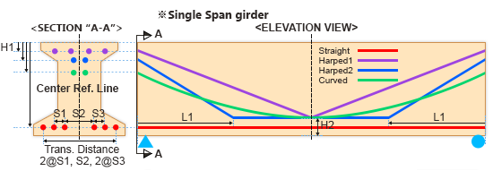
Section (End A-A) is represented end section of segment start
Elevation view is represented by segment grouping.
Zoom in, out and move the drawing is possible with the placing mouse in the drawing
Type
Specify the type of pattern for the tendon, such as straight, harped1, 2 and curved. Each type has minimum required dimension (D, H1~H5, L1,L2) that specify the tendon profile
Tendon property: Specify the tendon properties
Number of Tendons: Input the number of tendon in each layer.
Transverse Distance
Specify the distance dimensions related to the transverse tendon gap in the same layer profile
Distance can be possible input equal and unequal spacing and type in the form of “@” or “,”. For equal distance, type in the form of “number of distance@distance”.
In case of selecting the “Center” section reference line, placement of total tendon of each layer is located in the middle of transverse width. In case of selecting the “Left”/”Right” section reference line, Tendon is arranged in the transverse spacing from distance “D”.
D: Distance from the left and right section reference line. The left (right) end side of cross section is a section reference line when “Left” (“Right”) is selected in section reference line. It is deactivate when “Center” is selected in section reference line.


H1: A vertical distance from top of section in a start end position
H2: A vertical distance from bottom of section in the middle of 1st span position
H3: A vertical distance from top of section in the 1st support position
H4: A vertical distance from bottom of section in the middle of 2nd span position
H5: A vertical distance from top of section in the 2nd support position
L1: A longitudinal distance from 1st span start position
L2: A longitudinal distance from 2nd span start position
Basically, the tendon is placed with symmetric conditions
![]() Jacking stress
Jacking stress
Specify the pre/post-tensioning stress
![]() Grouting: after n stage
Grouting: after n stage
Define the stage at which the tendons are grouted in the ducts (sheathes). The grouting stage determines the timing of using the transformed section with the grouted tendons. Once the ducts are grouted, the transformed section properties are subsequently considered. The input signifies the timing of incorporating the transformed properties.
![]() Detailed…
Detailed…
Specify and modify the jacking stress and debonding tendon length of each tendon in detail.
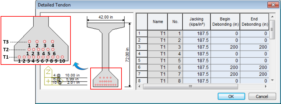
The entries in the “Name” column (T1,T2,…Tn) represent horizontal tendon layers starting from the lowermost tendon layer in the section
The entries in the “No.” column identify individual tendons in a particular layer starting from the left-most tendon.
![]() Tendon Assignment List
Tendon Assignment List
After finishing tendon definition of each table row in tendon assignment table, click “Add” to save the each tendon assignment of segments.
Name: Tendon assignment name are saved
Total Tendon: Summation of the total number of tendons in the segment. It is obtained by adding up the total number of tendons used in each row in the same tendon assignment name section.
![]() : Click to enter new or additional tendon placement in the tendon assignment table.
: Click to enter new or additional tendon placement in the tendon assignment table.
![]() : Select the tendon assignment list to be modified, then the upper tendon assignment table data is displayed and can be modified the data. Click
: Select the tendon assignment list to be modified, then the upper tendon assignment table data is displayed and can be modified the data. Click ![]() to modify the upper tendon assignment table data.
to modify the upper tendon assignment table data.
![]() : Select the tendon assignment list to be deleted and click
: Select the tendon assignment list to be deleted and click ![]() to eliminate a previously defined tendon assignment table data.
to eliminate a previously defined tendon assignment table data.