RC Slab Bridge
The Wizard automatically generates the influence surface model of a RC (Reinforced Concrete) slab bridge by entering simple variables.
From the Main Menu select Structure > Wizard > RC Slab Bridge
RC Slab Bridge Wizard consists of three tabs - Longitudinal, Transverse and Loads.
![]() Longitudinal tab
Longitudinal tab
Enter the material property type and longitudinal configuration of a bridge to auto-generate the bridge model.
![]() Model
Model
Material: Material property of the bridge
Size of Plate Element: Specify the maximum size of plate elements auto-generated in the longitudinal direction.
Span: Specify the spans sequentially.
Radius
Check in the box and specify the radius in the case of a curved bridge.
Convex: Convex curvature (center of circle located below)
Concave: Concave curvature (center of circle located above)
Radial Type: Spans and supports are laid out in a radial pattern.
Parallel Type: Support lines are laid out parallel to one another.
Note
Radial Type becomes activated for a curved bridge. If "Convex" is selected, spans become shorter towards the center of the circle.
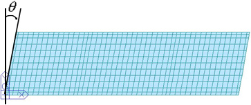
Skew: Skew angle of the bridge in plan (θ deg)
Note
Keep the pier directions uniformly for a curved bridge having a skew angle.
t, t1, a1, a2, a3: Referring to the guide diagram, enter the slab data in the longitudinal direction.
![]() Boundary
Boundary
Supports
Specify the location of a fixed support along the direction of the bridge.
Elastic Link: Provide Elastic Link for the bridge bearing.
Elastic Link Stiffness: Specify the stiffness of the Elastic Link in the translational directions.
Abut: Kx, Ky, Kz: Stiffness of Elastic Link on Buttress
Pier: Kx, Ky, Kz: Stiffness of Elastic Link on Piers
![]() : Select to enter the stiffness of the elastic link for each pier and buttress in each translational direction.
: Select to enter the stiffness of the elastic link for each pier and buttress in each translational direction.
Elastic Link Length: Enter the elastic link element. The magnitude does not affect the results of the analysis, as it is simply required to define the element.
Fixed Support: The locations of fixed supports are defined in both longitudinal and transverse directions. The fixed support lines are defined in both Longitudinal and Transverse tabs. Except for the cross point of the two support lines, all the remaining supports are released in the general directions of the support lines. The true directions are defined by Direction.
Direction: The restraint-free directions of the support bearings are determined by one of the two methods. The right hand rule applies to the perpendicular direction.
Tangential: The restraint-free direction is tangent to the longitudinal axis of the bridge. (ie. tangent to the curvature of a curved bridge or in the direction of a straight bridge)
in line with Fixed Support: The restraints are freed in the directions from the individual supports to the fixed support.
![]() Transverse tab
Transverse tab
Define the transverse direction (cross-section) type for barrier, median strip, sidewalk, etc.
Type: Transverse cross-section type
|
Type |
Left |
Right |
|
|
Barrier |
Barrier |
|
|
Barrier |
Median Strip |
|
|
Median Strip |
Barrier |
|
|
Barrier |
Without Median Strip |
|
|
Without Median Strip |
Barrier |
Size of Plate Element: Specify the maximum size of plate elements auto-generated in the transverse direction.
b1, b2, ~, D, n: Referring to the guide diagram, enter the transverse cross-section data.
Transverse Fixed Support: Enter the fixed supports in the direction perpendicular to the axis of the bridge, identified by the bearing numbers from the left looking in the direction of the axis of the bridge.
![]() Loads tab
Loads tab
Enter the load cases and loads required to analyze a RC slab bridge. Load cases and combinations are automatically generated in an auto-generated model.
Load Combinations
Factored: Factored load combinations are auto-generated.
Unfactored: Service load combinations are auto-generated.
Note
In V 6.3.0 we can specify loads by "KRTA-BRG2K, AASHTO-Std2K, AASHTO-LRFD02, IRC: 6-2000 and Taiwan", and options are activated depending upon each country code.
![]() : Select the moving load code of a country.
: Select the moving load code of a country.
Self Weight: Slab self weight
Pavement: Weight of pavement (pressure load)
Weight Density: Weight density of pavement
Thickness: Pavement thickness
Barrier: Barrier load (pressure load)
Self Weight: Self weight of barrier per unit length
Additional Load: Additional loads such as noise barrier, guard rails, etc.
Note
The linearly distributed loads entered for Barrier and Median Strip are divided by the widths entered in the Transverse tab and applied as pressure loads.
Median Strip: Self weight of median strip (pressure load)
Sidewalk: Superimposed weight of sidewalk
Thickness: Sidewalk thickness
Self Weight: Superimposed weight of sidewalk per unit volume
Crowd Load: Human occupancy load
Live Load: Bridge live load (It needs to be corrected comparing with AASHTO)
Class of Loading: Bridge live load grade, HS, HL, etc.
Eccentricity: Reference axis when the live load is applied eccentrically.
Settlement: Negative value
Note
When Settlement is entered, the settlements by the locations of the auto-generated support settlement group are automatically analyzed.
Temperature: Temperature difference between the top and bottom surfaces of the slab
Wind Load: Wind load acting on the bridge and noise barrier
W: Lateral wind load acting on the bridge and noise barrier
T: Moment due to the lateral wind load acting on the noise barrier.