Rail Track Analysis Model
Rail Track Analysis Model Wizard is provided to account for additional stresses and displacements due to an interaction between decks and rails.
1) Automatic modeling for a simplified separate analysis
Case 1 : Model with temperature loads without train loads.
Case 2 : Model that has sections, which have different resistances of ballast depending on the presence of train vertical loads, acceleration / braking loads
2) Automatic modeling for a stage analysis
Unloaded Stage : Stage where only temperature loads are included. The resistance of ballast for Unloaded Condition is applied to all sections.
Loaded Stage : Stage where acceleration / braking loads and train vertical loads are included. The resistance of ballast for Loaded Condition is applied to where the train load is applied.
3) Automatic modeling for a moving load analysis
Analysis is performed to find the location of the maximum additional stress by moving the train forward. When the train is moved forward, models that reflect the changes in boundary conditions are automatically created.
Note
Modeling cases that are automatically created are saved in the folder with the same file name.
From the Main Menu select Structure > Wizard > Rail Track Analysis Model.
![]() Layout
Layout
(1) Bridge Data
Bridge Material : Define material for the superstructure of a bridge by using material properties previously defined in Material Properties dialog box.
Deck Information : Input the number of decks and their lengths.
ex) 4@50, 70 : 4 decks of 50 m each and a deck of 70 m compose a bridge of 270 m.
Embankment Length : Enter the embankment length.
Span Type : Define support condition and span length for the bridge. The program provides four most frequently used types.
![]() : Span condition and span length can be tabulated as per the user's preference.
: Span condition and span length can be tabulated as per the user's preference.
Note
If the maximum number of span was entered as 4, then four slots will be available for span length. The values for the span lengths are to be entered sequently, which should not exceed the total length of the deck. If exceeded, the remaining slots will be locked once exceeded.
(2) Rail Data
Rail Material: Define rail materials by using material properties previously defined in Material Properties dialog box.
Number of Track: Enter the number of tracks (Max = 2).
Additional Check: Define additional verification conditions commonly applied to both cases.
Zero Lateral Resistance: Zero Lateral Resistance can be defined. When an additional stress exceed a certain level, zero lateral resistance can be installed to reduce the additional stress. It is defined with respect to the left end of the embankment and with zero resistance of ballast at the defined section.
Rail Expansion Joints: When Zero Lateral Resistance is not capable to reduce the additional stress to a certain level, Rail Expansion Joints can be installed. The location of Rail Expansion Joints refers to its left end when defined.
![]() Section
Section
(1) Deck Section
Bridge Section : Select cross section of a deck.
![]() : Check on when tapered section is to be defined for each of the span of the deck. Bridge Section is deactivated when this is checked.
: Check on when tapered section is to be defined for each of the span of the deck. Bridge Section is deactivated when this is checked.
Relative : The horizontal location of the section is assigned as a ratio with respect to the total length. It is applied in the same way for the span of a deck.
Note
When Start is chosen in Reference and Location is 0.1, the chosen section will be located at "0.1 times the span length" (called 0.1L point) point. If no section is defined at the 0 L point, then the same section as that in the 0.1L point will be used.
Section : Sections that have been defined in Bridge Section can be utilized by using the Add/Modify/Delete button.
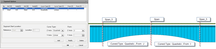
![]() : Sectional tapered form information can be defined. Data such as sectional and directional curve types are defined.
: Sectional tapered form information can be defined. Data such as sectional and directional curve types are defined.
Eccentricity between Rail/Slab : Eccentricity that arises between a rail and the center of a deck is defined.
![]() : Deck data (Bridge Section, Tapered Section Assignment Data) can be copied into other deck.
: Deck data (Bridge Section, Tapered Section Assignment Data) can be copied into other deck.
Apply all Deck Data : Currently defined Deck Data are applied to all of the decks left.
Section Applied Decks : Currently defined Deck Data is applied to those that are listed in Selected Decks.
(2) Rail Section
Rail Section : Rail cross section is defined.
![]() : Built-in rail cross sections can be added to Section Data.
: Built-in rail cross sections can be added to Section Data.
![]() : Track lane is located by giving a distance from the center of the section. When this is not defined, it is arbitrarily applied in modeling. The location of Track Lane has no effect of the analysis result but is used for model view.
: Track lane is located by giving a distance from the center of the section. When this is not defined, it is arbitrarily applied in modeling. The location of Track Lane has no effect of the analysis result but is used for model view.
![]() Boundary
Boundary
(1) Lateral Resistance Data
Ud (Lateral Limited Displacement) : Lateral Limited Displacement
Fmax (For Stress Check) : Resistance of Ballast used in stress check
Fmax (For Displacement Check) : Resistance of Ballast used in displacement check
Note 1
For the case of Ballast Bed, resistance of ballast is differently applied in stress check model and displacement check model when verifying temperature load.
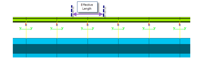
Note 2
If the unit of Resistance of Ballast force by unit length (ex. KN/m). Therefore, proper effective length is automatically multiplied to calculate the stiffness of Multi-Linear Elastic Link.
(2) Define Condition
Ballast type is defined between Ballast Bed and Concrete Bed.
![]() : Ballast type can be defined per section.
: Ballast type can be defined per section.
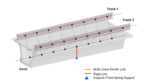
(3) Boundary
Spring Type : Pier Section is not directly used in modelling but supports and point spring supports are used. Dz, Rx and Rz are restrained for the boundary condition of a roller and the SDx value defined in Horizontal Stiffness is used for the horizontal stiffness of multi-linear elastic link.
Bearing Type : Horizontal stiffness can be entered or the bottom of pier can be restrained with Point Spring Support.
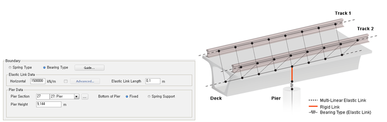
Elastic Link Data : Horizontal stiffness can be assigned. Elastic Link Length can be entered as well, which represent the height of the support. Vertical stiffness is internally defined as 10e7 kN/m.
![]() : Horizontal stiffness can be differently assigned per deck.
: Horizontal stiffness can be differently assigned per deck.
Pier Data : Pier section and pier height can be defined and the support condition at the bottom of pier can be defined either Fixed or Sprint Support.
![]() Load
Load
(1) Temperature Load
Element temperatures for deck and rail are defined.
(2) Acceleration / Braking / Vertical Load
Sectional Acceleration / Braking / Vertical Loads are defined.
With respect to the left end of the whole model, the range and load for sections are defined.
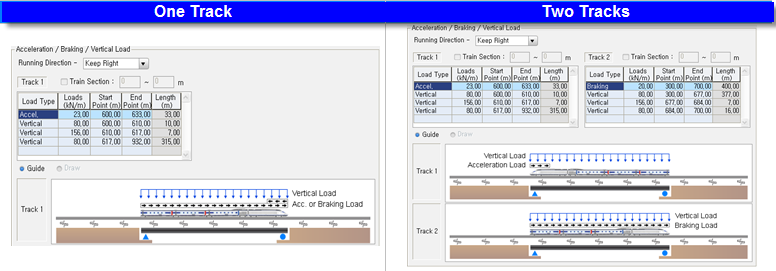
Running Direction : Train loads are applied based on the direction of the train traffic. Keep Right and Keep Left are the choices of traffic direction.
Train Section : When train vertical load is not defined, Lateral Resistance Data of Loaded Condition in Boundary tab is applied in the region specified in Train Section field.
Load Type : One of the Acceleration load and Braking load is applied for the case of one track. Acceleration and Braking loads are individually applied for the case of two tracks. Vertical train load can be defined with the different loading value by regions.
(3) Moving Load Data
Number of Track Loading Locations : This represents the number of location that the train load is applied. N number of location will generate N number of model files.
Location Increment for each Model : Increment in each track is entered.
Note
Number of Track Loading Locations : 3
Location increment of Track : 10m
This set-up will generate 3 additional model files whose the train has moved 10m, 20m and 30m, respectively.
![]() Wizard Option
Wizard Option
(1) Modeling Option
Element Length : Unit length for modeling is entered. Based on the entered element length, the effective length of rails and the resistance of ballast in Multi-Linear elastic Link are determined.
Unit Option: Unit for Element Length can be selected between meter and feet. This unit affects to the element length only. Unit system of other tabs/options can be specified using the Unit tool bar at the right bottom of the window or Tools > Unit System menu.
Note
Value greater than 2m is not permitted as per UIC specification.
(2) Analysis Model Option
1. Stress Check Model Option : Option that creates model files for additional stress check.
Simplified Separate Analysis Model : Creates model files for individual analysis.
xxx_Temp.mcb : model file that contains boundary conditions and a temperature load without train load.
xxx_Train.mcb : model file that contains boundary conditions and acceleration/braking/vertical loads as well as train load.
Complete Analysis : Creates model files for construction stages and complete state model file.
xxx_Complete.mcb : Model file that contains Unloaded stage (without train load) and Loaded stage (with train load)
2. Displacement Check Model Option : Option that creates model files for displacement check. For the case of Unloaded Condition of Ballast Bed, the resistance of ballast is different from that of Stress Check case. Displacement checks are only available in Simplified Sperate Analysis Model.
Relative Longitudinal Displacement Component due to Acceleration and Braking Alone: provides model files with individual analysis for longitudinal displacements between decks and rails due to acceleration and braking loads.
xxx_Add1_RelativeDosp.mcb : Displacement check file that contains acceleration/braking loads
Relative Longitudinal Displacement Component due to Vertical effects: provides model files with individual analysis for longitudinal displacements due to vertical train loads.
xxx_Add2_RotationAngle.mcb : Displacement check file that contains vertical effects.
Relative Longitudinal Displacement Component at Rail Expansion Joints: provides model files considering rail expansion joint with individual analysis for longitudinal displacements. (Temperature load in both rail and deck must be entered.)
xxx_Add3_ExpansionJoint.mcb : Displacement check file that contains temperature loads (rail/bridge).
Rail Break Gap Size: Model file to check Rail Break Gap Size. In order to check the Rail Break Gap Size, the location of Rail Break needs to be entered.
xxx_Add4_RailBreakGapSize.mcb : Rail Break Gap Size check file.