Steel Composite Bridge Wizard (Layout)
About Steel composite girder wizard
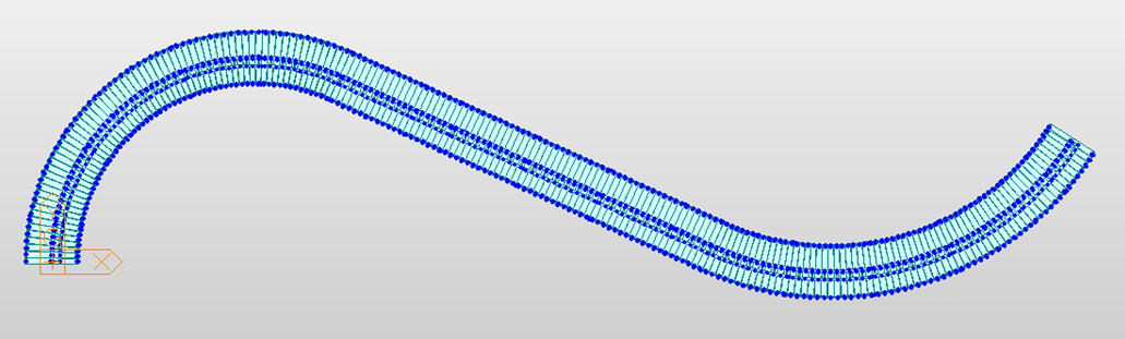
The fundamental objective of using the Steel Composite Bridge Wizard is to generate 3D finite models with ease in a relatively short time. Straight, curved, and skewed bridges can be modeled with various bracing conditions and substructure types. Also, both of Frame and plate elements can be used for modeling. Loadings and construction sequences can also be defined using the straightforward inputs and intuitive interface of the wizard.
Wizard configurations
The wizard consists of the four main Tab. The first tab (Layout) is for defining the basic geometry of a bridge and support properties. The second tab (Section) is for defining the material and section properties and also defining the locations of girders and beams with spacing or division information. The third (Load) and fourth (construction stage) tabs are to define the load and construction stage conditions
Due to unshored construction processes, the loads applied on steel composite sections are different in before composite and after composite states. Users can specify the exact states of loading conditions depending on the construction stages.
All Wizard input can be saved into a “*.wzd” file format.
 : Open an existing wizard file saved as *.wzd file type in the Steel Composite Bridge Wizard. By opening the file users have worked on before, users can re-execute, check, and modify the previously entered data.
 : Save the data entered in the Steel Composite Bridge Wizard as the *.wzd file type.
Using the wizard, full steel composite bridge models can be generated. Define the overall layout of the bridge geometry, boundary conditions, etc. in the Layout tab.
From the Main Menu select Structure > Wizard > Steel Composite Bridge Wizard > Layout
![]() Girder Type
Girder Type
Select one of the following girder types for the bridge:
Composite Steel I
Composite Steel Box
Composite Steel Tub
The deck and girders can be modeled in different modeling approaches: all frame, all plate, deck as plates and girder as frames, and deck and flange as plates and web as frames.
All Frame
Use frame elements for the entire model. This option is ideal for conventional straight bridges and can increase the efficiency of analysis times.
The All Frame type supports every girder type – the composite I, box, and tub types.
All Plate
Use all plate elements for the model. This option is ideal for curved or skewed bridges which requires more detailed analysis than simple bridges. Frame elements with section property cannot consider the effects due to torsion with differences in section angles due to skews or curves. Therefore, the All Plate option can be used for the bridges with complex geometry.
Only the composite I-girder type is supported by the All Plate approach.
Deck as Plates & Girder as Frames
Use plate elements to model the deck and frame elements to model the girders.
The composite I, box, and tub girder types are supported by this option.
Deck & web as plate, flanges as frame.
Use plate elements to model the deck and web, and frame elements to model the frame.
Only the composite Steel I section are supported by the All Plate type.
Note
Depending on the girder type (I, Box, & Tub) and modeling approach (All Beam, All Plate, …), the input menus are customized.
Only frame elements are used to model bracings and substructures regardless of the modeling approach selected.
![]() Span Information
Span Information
Specify the span length(s) in order.
(e.g. “300, 400, 2@300, 100” indicates that the first through the fifth spans are 300 ft, 400 ft, 300 ft, 300 ft, and 100 ft long each.
The span information is for the Reference Line. If the bridge model is skewed and/or curved, any span information should be taken from the Reference Line position.
Note
Also, the distances of deck element spacing, and distances of bracing spacing are based on the Reference Line.
![]() Deck Width
Deck Width
Specify the total deck width of the bridge. The deck width is used to indicate the deck width of the entire bridge. This information is used to create any dummy deck member or to suppress the deck information in the section properties for the All Plate or Deck as Plates and Girder as Frames modeling types.
![]() Support Skew Angle
Support Skew Angle
Specify the skew angle of each support position of the bridge in plan (θ deg). The skew angle must be between -75 and 75 degrees. This angle is applied to each support or pier unless the Advanced option which is used to specify varying skew conditions is used.
![]() Layout offset
Layout offset
Distance between the reference line and the center line of the bridge.
![]() Radius
Radius
Specify the radius for a horizontally curved bridge.
Convex: Convex curvature (center of circle located below the curve)
Concave: Concave curvature (center of circle located above the curve)
![]() Multi-Curve
Multi-Curve
Select Curve Data or Coordinate Data as an input method and click  to input multiple curves
Curve Data: Using the Multi-Curve Advanced option, the curvature can also be defined for a combination of straight and curve geometries.
Plan Curve
Define the horizontal curve(s).
Straight Line: The start and end location of the straight line.
Circular Curve: The start and end locations of the plan curve with specified radius of the curve point.
Transition Curve: The start and end locations of the transition curve with specified radius of the curve point.
Vertical Curve
Station: The station of the vertical curve
ELEV.: The elevation of the vertical curve
Curve Length: The horizontal length of the vertical curve
Bank Rotation
Station: The station of the bank rotation
Super Elevation: The super elevation of the bank rotation.
Example
|
Station (m) |
ELEV. (m) |
Curve Length (m) |
|
|
1 |
0 |
0 |
0 |
|
2 |
50 |
20 |
40 |
|
3 |
100 |
0 |
0 |
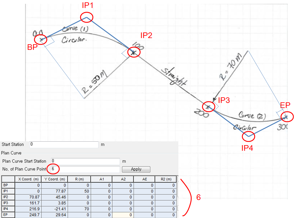
Coordinate Data: Using the Multi-Curve Advanced option, the curvature can also be defined for a combination of straight and curve geometries.
Start Station: The start station of bridge modeling
Plan Curve
Define the horizontal curve(s).
Plan Curve Span Start: start station of plan curve
No. of Plan Curve Point: Number of Plan Curve points. At least two of the plan curve points are required for the beginning point (BP) and the end point (EP). If the bridge has more than one curve or is a combination of curve and straight geometries, the number of plan curve point is equal to or greater than three. If three or greater number is input for the number of plan curve point, additional intermediate points (IP 1 for three plan curve pints, IP 2 for four plan curve points, …)
BP: The beginning point of the plan curve
EP: The end point of the plan curve
IP 1, 2, …: The intermediate points. (IP 1 for three plan curve pints, IP 2 for four plan curve points, …)
X Coord.: the x coordinate of the curve point
Y Coord.: the y coordinate of the curve point
R: The radius of the curve point
A1: The parameter of BTC(Beginning of Transition Curve)
A2: The parameter of ETC(End of Transition Curve)
AE: The parameter of egged shaped clothoid curve
R2: The 2nd radius of egged shaped clothoid curve

Vertical Curve
Station: The station of the vertical curve
ELEV.: The elevation of the vertical curve
Curve Length: The horizontal length of the vertical curve
Bank Rotation
Station: The station of the bank rotation
Super Elevation: The super elevation of the bank rotation.
Example
![]() Boundary
Boundary
-
Bearing Type
When the superstructure and substructure are connected with bearings:
Supports: Bearings are represented by fixed or simple support. Once the position of fixed support is determined, all the other supports are considered as free support longitudinally.
Elastic Link: Bearings are represented by elastic links. Enter the stiffness of bearings in each degree of freedom (Dx, Dy, Dz, Rx, Ry, & Rz) for the abutments and the piers. Click the option to enter different stiffness for different elastic link stiffness.
-
With Substructure
Substructure is included in the model. Define the following parameters for the Abutment, Elastic Link Stiffness, and Pier. The model includes and models the substructure with this option.
Abutment
Bearing Type
Fixed: Abutment set as fixed support
Elastic Link: Bearings are represented by elastic links. Enter the stiffness of bearings by directions for the abutments and the piers. Click to enter different stiffness for different supports.
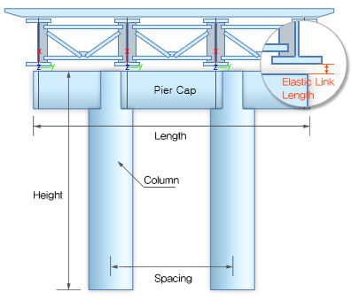
Pier
Pier Cap
Check the option if the pier has a pier cap
Section
Select the section to be used for the pier cap.
Click  to add a new section or modify an existing section.
Length: Transverse length of the pier cap
Material
Enter the material property to be used in the pier structure.
Click to add a new material or modify an existing material.
Pier Support
Fixed: Fix support is applied to the bottom of the pier.
Spring Support: Spring support is applied to the bottom of the pier.
Spring Stiffness:
Enter the horizontal and vertical spring stiffness values.
Click the to input different stiffness for different supports.
Column
Section
Select the section to be used for the pier.
Click to add a new section or modify an existing section.
Height
Enter the height of the pier. Click to enter different heights for different piers.
Spacing
If more than two columns are needed to be defined, specify the distance between the columns. If more than three columns, different spacings are input with commas (e.g. “10, 12” or “2@10”)