Steel Composite Bridge Wizard (Section)
Define the girder and bracing detail properties.
From the Main Menu select Structure > Wizard > Steel Composite Bridge Wizard > Section
![]() Deck Thickness
Deck Thickness
Specify the deck thickness.
For the All Element type (refer to the Layout – Girder Type), this value is used for the section thickness of transverse dummy section.
For all other modeling approaches, this value is used as thickness of plate elements for deck modeling approaches.
![]() Haunch Height (All plate, Deck as a plate, Deck & Web as a plate element type only)
Haunch Height (All plate, Deck as a plate, Deck & Web as a plate element type only)
Specify the distance between the deck and the girders, the gap is connected by rigid links, and the longitudinal spaces are determined by the size of the plate element. If the haunch is zero, no gap is created between the deck and girder. If the haunch is not zero, gap is created accordingly with rigid links linking the gap.
![]() No. of Girders
No. of Girders
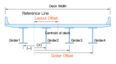
The offset to each girder center is input in the table.
![]() Girder Offset
Girder Offset
Distance between the reference line and the center line of each girder
The offset is negative when the offset is on the left side of the reference line in the longitudinal direction; the offset is positive when the offset is on the right side of the reference line in the longitudinal direction.
![]() Material
Material
Deck
Select the material property to be used in a deck element.
When the All Frame type is used, the selfweight of the deck is included. Also, based on the deck material selected, the wizard newly creates an additional material with the same properties as the deck but with zero weight density. For the All Frame type, like a Grillage modeling approach, transverse dummy beams are required for the transverse stiffness of the deck.
Girder
Select the material property to be used for the girder element. The SRC material type (Steel Reinforced Concrete with both steel and concrete properties) is selected for the girders.
Bracing
Select the material property to be used for the bracings.
Click  to define a new material or modify an existing material.
![]() Transverse Deck Element (All frame element type only)
Transverse Deck Element (All frame element type only)
Spacing: Select one of the following options to define the spacing of the Transverse Deck Elements
Distance
Enter the distance to be used for the spacing of transverse deck element.
Divisions
Instead of spacing, the number of divisions can be used to locate the transverse deck elements.
Divisions per Span
Determine the number of division for each span. (e.g. “3@5” or “5,6,5” for a three-span bridge)
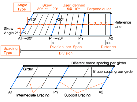
Angle type: Select one of the following options to define the skew type of the transverse deck elements.
Skew
If the Skew is selected, the Angle cell is disabled and the program uses the skew angle defined in the Layout Tab. If skew angle vary among the support, the skew angle for the transverse deck elements are interpolated.
(e.g. support skew angle is -30, -20 and internal division is 5, then each 4 internal angles are -28,-26,-24 & -22)
Perpendicular
The transverse deck elements are perpendicular to each girder.
User Defined
The angle is defined manually.
Note
A rectangular section for the dummy deck are automatically generated with the Deck Thickness & the Transverse Deck elements spacing length.
Mesh size for the All plate, Deck as Plate and Deck & Web as Plate types only)
Specify the size of the plate element for the deck.
Size of Plate Element
Specify the size of plate element for deck, web and flange.
Size of Web Element
Specify the plate element for the web in case the All Plate and Deck & Web as Plate types are selected.
![]() Bracing Information
Bracing Information
A bracing system stabilizes the main girders, contributes to the distribution of load and provides restraint to compression flanges or chords where they would otherwise be free to buckle laterally.
With the Wizard, the Bracing systems such as X brace, V brace & Inverted V brace can be defined.
By checking the “Different Support Bracing” option, different bracing types can be defined for the intermediate bracings and support bracings.
When only one type of bracing is needed, the first row is needed; When bracing types between girder lines are different, each table row is generated. It is controlled with the “Different Brace spacing per girder” options.
When the support bracing type is different from the intermediate, the support bracing is defined additionally.
Bracing Details: Bracing parameters are defined.
When click next to the “Bracing Details…”, the bracing information illustration can be viewed.
Type
Bracings or single beam type can be selected. When Click next to the "Bracing Details…", the following illustration can be reviewed.
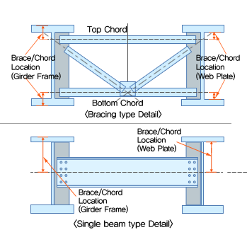
Bracing
Bracings as shown in the Bracing Type Detail.
Single beam
Single beam as shown in the Single Beam Type Detail.
Bracing Parameter
Brace Element Type: Specify the element type for the brace members.
Truss
Bracing elements will only transmit axial forces (no rotation allowed)
Beam
Bracing elements will transfer both force and moment.
Different sections can be used for each member.
Enter the section property to be used for the top and bottom chord and brace elements.
Click to add a new section property or modify an existing one.
Top: Specify the top chord member. When checked, the top chord will be included in the bracing system. Select the frame section property in the section list.
Brace: Specify the brace section. When checked, specify the type of brace : X, V, or inverted V brace.
Type

Bottom: Specify the bottom chord section. When checked, the bottom chord will be included in the bracing system. Select the frame section property in the section list.
Brace/chord location
Gap between Top Chord/Brace End & Top Girder Flange
Input a distance value in the current units for the change of the top of the chord/brace and the top girder flange.
Gap between Bottom Chord/Brace End & Bottom Girder Flange
Input a distance value in the current units for the change of the bottom of the chord/brace and the bottom girder flange.
 : Create the bracing based on defined parameters. Click the "Add" to define additional bracing type.
 : Click the bracing name that needs to be modified. Change the parameters. At the end, click “Modify” to save changes.
 : Click to delete bracing.
Spacing: Select one of the following options to define bracing locations.
Distances
The bracing locations can be defined by inputting the distances between the bracings. This distance information is applied for the entire length of the bridge.
Divisions
The distance between each bracing is the entire length of the bridge divided by the number entered.
Divisions per Span
The number of division per span can be entered.
(e.g. “8, 10, 8” can be input for a three-span bridge in which the bracing is applied to make 8, 10 and 8 divisions in the three spans.)
Different Brace spacing per Girder
Check to vary the brace spacing for each girder. When checked, the number of table rows increase as much as the number of girders.

When the “Different Bracing per Girder” option is checked off, only the first row of the table is shown.
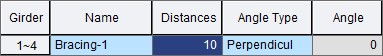
Girder 1~n: This bracing information applies to the between 1st and nth girders.
When the “Different Bracing per Girder” option is checked, the bracing information can be input for different girder sets.
Girder n~n+1: The bracing information is applied to the between nth and n+1th girders.
Name: Select the bracing type name pre-defined in the Bracing Details
Distance/Division/Division per span: The bracing locations can be input with the spacing distance length, the number of divisions or the number of division per span.
Angle type: Select one of the following options to define the skew type of the bracing.
Skew
If the Skew is selected, the Angle cell is disabled and the program uses the skew angle defined in the Layout Tab. If skew angle vary among the support, the skew angle for the bracings are interpolated.
(e.g. support skew angle is -30, -20 and internal division is 5, then each 4 internal angles are -28,-26,-24 & -22)
Perpendicular
The bracings are perpendicular to each girder.
User Defined
The angle is defined manually.
Different Support Bracing
Check on to vary bracings at the support locations from the general intermediate bracing types.
Select each support section that already defined in bracing details
Support: Each row in table represents the number of support positions. Each support conditions can be defined separately.
Name: Select the support bracing type name that was defined in the Bracing Details
Angle type: The Angle of the support bracing can be specified; it is applied to every support bracing.
![]() Girder Information
Girder Information
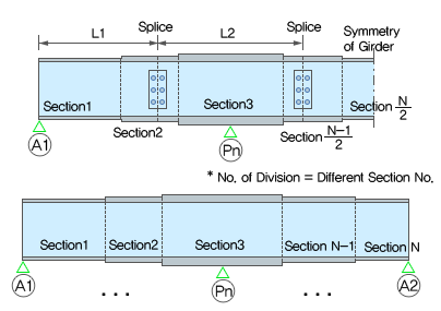
The girder sections can vary and be optimized for different parts of the bridge in order to have more economical design.
No. of Divisions
Define the number of division along the girder line.
For each division, select the section and the start and end positions of the division.
Symmetry
When the Symmetry option is checked, the division information is applied symmetrically. With the Symmetry option, the program will reduce the number of rows in the Girder Information table and make the bridge symmetrical.
(e.g. If the division number along the girder line is 5 and the Symmetry option is checked, only the Division No.1, No.2 and No.3 rows show in the Girder Information table. Then, the program generates symmetrical geometry based on the information for the half of the bridge.)
Name: Select the section for the girder
Start/End: Input the span start and end location.
The girder division start and end positions are based on the reference line (refer to the Layout tab for the reference line). Bridges with curve or skew can have different division length and start/end positions if the measurements are not taken from the reference line. Therefore, the span and end position should be taken based on the reference line only for the curved and/or skewed bridges.
Copy to Current Girder Data to Other Girders: Click to apply the same girder division information to the other girder lines.
Select the girders in the List and move to the Selected List
Click “OK” to complete copying the girder data to other girders.
Stringer
Check on to enter stringer properties
The stringers are modeled with frame elements between each girder
Define Girder Section

Define the section(s) to be used for the girder. The girder section must be one of the Composite Steel I, Composite Steel Box, and Composite Steel Tub.
Splice
When the “Splice” is checked, check the Define Splice Location option. The girder is divided into the several pieces by splice locations. Multiple locations can be entered and separated by commas. If multiple locations are entered, the first location is measured from the span start and next location is measured from the previous location.
(e.g. For a 30-ft-long girder with the splice locations at every 10 ft, “2@10” or “10,10” can be entered for the Splice Location.)
Generate the 10th Points elements
Check to generate the 10th points along each span.