Transverse Analysis Model
Automatically generate a transverse analysis model from the frame of a bridge in the primary direction. Upon selecting a point in the primary direction, the Wizard generates a 2 dimensional Frame model, which intersects the point. And this generates the section properties for analysis. In addition to the geometrical section properties, the user can also assign loads (such as dead load, live load, etc), tendons and reinforcement to the elements.
From the Main Menu select Structure > Wizard > Transverse Model
![]() Selection Position
Selection Position
Element: Select elements for which transverse models will be created.
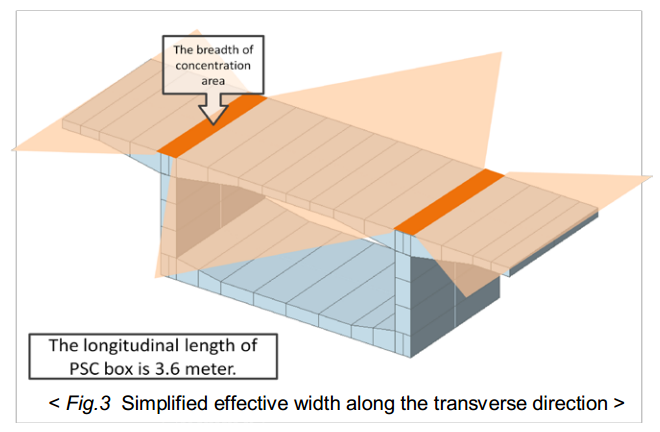
Grillage Model (PSC-T shape only): When using a Tee-section grillage model, its design should consider the transverse section of the entire bridge. By selecting this option, the program creates a transverse section for the entire bridge. However, this only applies to the PSC Tee-girder sections.
After selecting this option, if the user selects the elements that compose the transverse section in a particular order, the program automatically generates the entire transverse section by connecting the sections in the order they were selected.
Position
Select the node position (or node) for creating the transverse section model. By clicking on the ![]() button after selecting the elements and position, the selected elements are listed, and the transverse frame appears in the View Dialog box for preview. The preview is useful for inputting tendons and reinforcement. X indicated under the data part of the list indicates that the information for creating the transverse model has not been entered. After entering the information in Model, Load and Tendon & Reinforcement tabs, and clicking on the
button after selecting the elements and position, the selected elements are listed, and the transverse frame appears in the View Dialog box for preview. The preview is useful for inputting tendons and reinforcement. X indicated under the data part of the list indicates that the information for creating the transverse model has not been entered. After entering the information in Model, Load and Tendon & Reinforcement tabs, and clicking on the ![]() button, O is displayed, which signifies that the transverse model is ready to be generated.
button, O is displayed, which signifies that the transverse model is ready to be generated.
![]() Selection Position
Selection Position
Shape: Displays the assigned sections of the selected element. The data inputted in Transverse Analysis Model Wizard (Model, Load, and Tendon & Reinforcement) should be based on the shape indicated in the Section.
-
Model tab
Input the geometric properties for the transverse section model..
Longitudinal Length: Longitudinal length of the transverse section model.
Maximum Mesh Size: Maximum mesh size for the transverse section model.
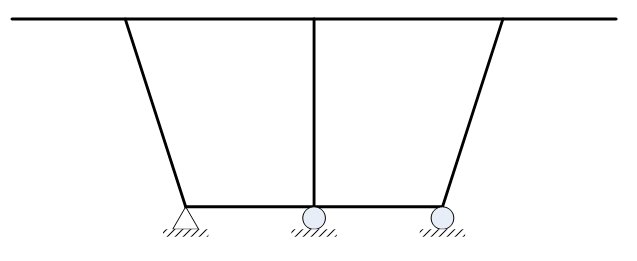
Boundary Condition: Type of Boundary condition.
Boundary condition is defined for every node at the bottom of the section. The left-most side node is defined as a hinge and the other nodes are defined as roller.
Support: Define boundary condition as a Support
Spring: Define boundary condition as Point Spring Support.
![]() Pavement & Barrier
Pavement & Barrier
Define the section of Pavement & Barrier.
Type: Select the transverse shape.
Slab Width: The slab width of the section shape selected above is displayed. This cannot be modified.
b1~b7: Define the length by referring to the figure in the dialog box. These are the positions where the loads are applied. Assigning the length as zero is allowed.
Sum: The sum of b1~b7 is indicated.
![]() Change the Section Offset
Change the Section Offset
It is invoked if a section offset is assigned to the Top or Bottom flange for the creating the transverse model. If the transverse model requires a tendon, selecting Center Top for the top flange offset is convenient, since the coordinate of the tendon is inputted based on the axis of the flange element.
Top Flange/Bottom Flange: Assign the section offset to the section of Top and Bottom flanges.
Center-Top/Center-Bottom: Assign Center-Top to the top flange section and Center-Bottom to the bottom flange section to generate the section offset.
Offset Distance: User defined offset distance is assigned to the flange section. Top flange offset distance is measured from the top of the section, and Bottom flange offset distance is measured from the bottom. The offset distance is based on the center of the section.
Consider Joint Offset of the Flanges and Webs
This option is checked if the rigid zone of the flange web intersection is considered.
Reverse Local-y Axis
The section will be reversed by local y axis.
The figure shown below is an unsymmetrical Tee section.
A model will be created as shown below, if the section shown above is created as a transverse section model by selecting the Reverse Local-y Axis. The figures below show the front view created by the Wizard with "Hidden" applied.
-
Load tab
Assign the load information
Self weight: Self weight
Pavement: Weight of Pavement.
Thickness: Thickness of pavement
Unit Weight: Unit Weight of pavement
Barrier: Weight of barrier. Input "Section x Unit weight" In the transverse model, the thickness of the barrier is considered when assigning the load.
Unit Load: Self weight of Barrier
Additional Load: Additional load on the barrier due to sound proof wall, or railing.
Median Strip: Self weight of median strip. Input "Section x Unit weight" In the transverse model, the thickness of the median strip is considered when assigning load.
Collision: Assign load due to collision.
Height: Assign height of collision.
Side Walk: Self weight of Side Walk
Thickness: Thickness of Side Walk
Unit Weight: Unit weight of Side Walk
Crowd load: Pedestrian load.
Handrail Force: Calculates the load when a person is leaning on the hand rail. The size of the load and the distance between the top flange and the load are inputted.
Temperature
Delta T: Distribution of heat and temperature difference of the top and bottom surface.
System Temperature: Load caused by temperature
Live Load
Assign the moving load for transverse analysis.
P: Wheel load
n: Number of lanes
De: Minimum distance of the wheel to the barrier or the median strip.
Dw: Distance between two wheels
Dv : Wheel distance between two vehicles.
![]() : Load reduction factor to be applied when vehicle loads are loaded on a number of traffic lanes.
: Load reduction factor to be applied when vehicle loads are loaded on a number of traffic lanes.
![]() : Load reduction factor to be applied to a position on the transversal section.
: Load reduction factor to be applied to a position on the transversal section.
Wind Load
Input wind load data
Distributed Load on the Web: Uniformly distributed load on the Web
Horizontal Load on the Barrier: Lateral load acting on the barrier
Moment due to the Barrier: Moment occurring on the barrier due to the lateral load.
Direction: Direction of the wind load.
-
Tendon & Reinforcement tab
Assign tendon prestress and reinforcement information.
![]() Tendon
Tendon
Tendon Property: Select tendon property. In case the predefined property does not exist or when the existing property needs to be modified, click on the [ ] button to the right.
Numbers: Enter the number of tendons in the primary direction. This is the number of tendons that are included inside the primary length inputted in the Model Tab.
Prestress Load: Enter the prestress load. This can be inputted as force or stress.
Direction: Enter the direction of the stress.
Curve Type
Spline: Calculate the minimum polynomial curvature connecting the points defining the tendon profile and automatically place the tendons.
Round: Place the tendons in along a circle, which form tangents to the straight lines connecting the points defining the tendon profile.
Profile Insertion Point
Input the starting coordinate of the tendon based on the coordinates created from the beam element corresponding to the top flange.
x-axis Direction:
This is the x-axis that is defined for locating the tendon.
Profile
Place the tendon profile by defining the coordinates of the tendon. The tendon coordinate system (TCS) used here is temporary, and its origin is the starting point of the tendon, which will be related to the elements by the profile insertion point. As many coordinates as required to define the profile may be specified, but at least two (start and end) points are required. The x-axis of TCS is parallel with the Global axis in the longitudinal direction, and the z-axis of TCS coincides with the Global Z-axis. See Tendon Shape below for further details.
x, y, z: tendon coordinates in TCS.
fix: check on the box to specify the tangent to the tendon curvature at the point in question.
Ry: if "fix" is checked, the angle of the tangent line relative to the x-axis in the TCS x-z Plane.
Rz: if "fix" is checked, the angle of the tangent line relative to the x-axis in the TCS x-y Plane.
![]() Reinforcement
Reinforcement
Assign reinforcement in the transverse direction.
Assign Element
Select the elements to assign transverse reinforcement. The elements are selected by first clicking on preview and then clicking on ![]() . The number of the selected elements is then assigned automatically.
. The number of the selected elements is then assigned automatically.
If all the elements are selected, then without clicking ![]() all the element numbers are automatically inputted.
all the element numbers are automatically inputted.
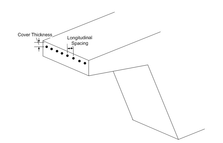
Cover Thickness
Input Cover Thickness after deciding if top or bottom reinforcement is needed.
Size
Select the diameter of reinforcement.
Numbers
Input the number of rebars in the transverse direction.
Longitudinal Space
Input the longitudinal spacing for transverse reinforcement.
After inputting the information by clicking on ![]() , "O" is displayed on the data list of the elements. After "O" is confirmed, click on the
, "O" is displayed on the data list of the elements. After "O" is confirmed, click on the ![]() button to create a transverse model file. The transverse model file is saved in the same folder where the current primary direction bridge model is saved. The file will be saved as follows:
button to create a transverse model file. The transverse model file is saved in the same folder where the current primary direction bridge model is saved. The file will be saved as follows:
(The file name of primary direction model)_(Element number)-(i or j).mcb
For example: FCM Bridge_14-i.mcb
![]() Defaults all the values.
Defaults all the values.
![]() Revision of Civil 2014 (v2.1)
Revision of Civil 2014 (v2.1)