Divide Elements
Divide selected elements and create nodes at the division points.
From the Main Menu select Node/Element > Elements > Divide
Shortcut key: [Alt]+7
|
Click
|
Equal Distance: To divide at equal distances
Frame
Number of Divisions x: Number of divisions in ECS x-direction
Planar
Number of Divisions x: Number of divisions in ECS x-direction
Number of Divisions y: Number of divisions in ECS y-direction
Solid
Number of Divisions x: Number of divisions in ECS x-direction
Number of Divisions y: Number of divisions in ECS y-direction
Number of Divisions z: Number of divisions in ECS z-direction
Unequal Distance: To divide at unequal distances
Frame
Enter unequal distances as many times as desired in ECS x-direction.
Planar
Enter unequal distances as many times as desired in ECS x-direction.
Enter unequal distances as many times as desired in ECS y-direction.
Solid
Enter unequal distances as many times as desired in ECS x-direction.
Enter unequal distances as many times as desired in ECS y-direction.
Enter unequal distances as many times as desired in ECS z-direction.
Parametric Unequal Distance
Unequal distances defined in terms of distance ratios
Frame
Ratio x: Relative unequal distance ratios in ECS x-direction
Planar
Ratio x: Relative unequal distance ratios in ECS x-direction
Ratio y: Relative unequal distance ratios in ECS y-direction
Solid
Ratio x: Relative unequal distance ratios in ECS x-direction
Ratio y: Relative unequal distance ratios in ECS y-direction
Ratio z: Relative unequal distance ratios in ECS z-direction
Parallel Bracing
Parallel Bracing is applicable for a structure with two posts such as a truss structure of a transmission tower. If the space between the two posts is connected by bracings, nodes are created and the post elements are divided so that the inclination of the bracings is constant irrespective of the inclination angle of the posts. The bracings so created are parallel to each other.
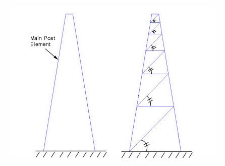
Number of Divisions
![]() Main Post Element (E1, E2): Assign two posts that will be connected by bracings
Main Post Element (E1, E2): Assign two posts that will be connected by bracings
Divide by Node
Select an element and a node. Divide the element into two new elements using the node.
![]() Element to be divided: Element being divided
Element to be divided: Element being divided
![]() Node to divide element: Node dividing the element
Node to divide element: Node dividing the element
Note
The Node to Divide Element dose not necessarily have to be on the Element to be Divided.
Divide by Pattern
Divide planar elements according to a defined pattern. Select the planar elements to be divided. The Base Edge or the Base Point, which forms the basis for dividing, will appear as reference in the Model Window.
Divide Planar Elements using a Base Edge
|
1.Select a division Pattern. |
|
|
|
2.Select a Base Edge that will become the reference of division for the selected elements. |
|
|

Divide Planar Elements using a Base Point
|
1.Select a division Pattern. |
|
|
|
2. Select a Base Point that will become the reference of division for the selected elements. |
|
|

Divide Planar Element using a Defined Pattern
|
1. Select a division Pattern. |
|
|
Note
Base Edge and Base Point define the application direction of a Pattern. They do not affect the structural analysis.
Merge Duplicate Nodes
Merge overlapping nodes to single nodes if new nodes coincide with existing nodes. Click ![]() to modify the Merging Tolerance.
to modify the Merging Tolerance.