Section
Enter section properties for line elements (Truss, Tension-only, Compression-only, Cable, Gap, Hook, Beam Element).
From the Main Menu select Properties > Section > Section Properties.
![]() To enter new or additional section properties
To enter new or additional section properties
Click ![]() in the Properties dialog box and enter the following: Enter the
section properties by entry types.
in the Properties dialog box and enter the following: Enter the
section properties by entry types.
![]() Modification of previously entered section data
Modification of previously entered section data
Select the section to be modified from
the list in the Section dialog box and click ![]() to modify the related data.
to modify the related data.
![]() Removal of previously entered section data
Removal of previously entered section data
Select the section to be deleted from
the list in the Section dialog box and click ![]() .
.
![]() To copy previously entered section data
To copy previously entered section data
Select the section to be copied from
the list in the Section dialog box and click ![]() .
.
![]() To modify section data from an existing fn.MCB file
To modify section data from an existing fn.MCB file
Click ![]() and select the MCB file containing the section data or specify
a file name then click
and select the MCB file containing the section data or specify
a file name then click ![]() . [Details]
. [Details]
Section
List
Display section data contained in the existing fn.MCB file.
Selected List
Select section data to be imported and register them in the
Selected List.
Note
If a fn.MCB is selected, all the section data contained in the
existing fn.MCB file are registered in the Selected List.
Numbering Type
Specify the Import mode for section numbers.
Keep ID
Import the data keeping the same section numbers.
New ID
Assign new numbers to the imported section data.
![]() To modify previously entered section property numbers
To modify previously entered section property numbers
Select the section property
numbers to be renumbered from the list in the Properties dialog
box and modify the related data followed by clicking ![]() .
[Details]
.
[Details]
Start number
Assign a new starting number for the material to be modified.
Increment
Enter the increment for numbering material property numbers.
Change element's material number
Modify a material property number. Using this option will modify
the previously defined material property number. If this option
is not checked, the selected material having previously defined
number will become undefined and the additional user-defined
material number will be created without any assigned elements.
![]() Section ID
Section ID
Section number (Auto-set to the last section number +1)
Note
Up to 999999 Section ID's can be assigned.
![]() Name
Name
Section name (Sect. Name by default if not specified)
![]() Offset
Offset
Display
the section Offset currently set. Location of the Centroid of
a section is set as default. Click ![]() to specify a section Offset away from the Centroid. Use
to specify a section Offset away from the Centroid. Use
![]() Hidden
to verify the input. [Details]
Hidden
to verify the input. [Details]
Offset: Specify the section Offset from the location options shown in the figure below.
Horizontal Offset: Specify the Offset in the transverse direction. "to Extreme Fiber" assigns the offset to the outer-most point. For a specific location of Offset, select 'User"and enter the distance from the "Centroid" to the desired Offset location. Unless the Offset is "Center-Center" the Horizontal Offset can be entered as the "User" type. For a tapered (non-prismatic) section, data input for the J-end also becomes activated.
Vertical Offset: Specify the Offset in the vertical direction. "to Extreme Fiber" assigns the offset to the outer-most point. For a specific location of Offset, select "User" and enter the distance from "Centroid" to the desired Offset location. Unless the Offset is "Center-Center" the Vertical Offset can be entered as the "User" type. For a tapered (non-prismatic) section, data input for the J-end also becomes activated.
Note 1
When Offset distance is specified, a positive (+) sign applies to Center-to-outward for Centroid reference and Extreme-to-inward for Extreme Fiber reference.
Note 2
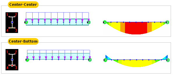
Node-based loads such as Nodal Loads and Specified Displacements are always applied at the nodes. However, element-based loads such as Beam Loads and Temperature Loads are applied on the center line of the element section. Please find the difference in the following example.
User Offset Reference: When section offset distance is specified as the "User" type, define the reference location.
Centroid: Specify the offset distance relative to the centroid of the section.
Extreme Fiber(s): Specify the offset distance relative to Left/Right & Top/Bottom.
Note 3
When User type is specified, the Offset distance and direction are entered relative to Centroid irrespective of the Center option (Centroid or Center of Section). For example, specifying "Offset: Left-Center", "Center Loc.: Center of Section" and "Horizontal offset: 0.5 " User type" will result in an Offset 0.5" to the left of the Centroid. And if the Offset option is "Left-Center" and the Center option is Center of Section the User type for Horizontal offset becomes activated and the User type for Vertical offset becomes inactivated. The Horizontal offset defined as User type here becomes the Centroid, and the Vertical offset fixed to Center becomes the "Center of Section"
Note 4
When FCM Wizard is used, and "Apply the Centroid of Pier Table Section Option" is selected, the node locations of the girder will be changed as follows:
Offset: Center-Top
User Offset Reference: Extreme Fiber(s)
Vertical Offset: User, Offset Distance (i & j) = Pier Table section height-Centroid of Pier Table section
Internal process of section offset
A beam element is defined by two nodes and a line connecting the two nodes. This line becomes a reference line representing the beam element, which usually coincides with the neutral axis of the beam element. If a section offset is assigned to a section, the neutral axis of the member shifts by the specified offset distance, and the element reference line is placed at the offset location. The reference line is used for selecting the element, assigning loads, displaying member forces, etc. The offset of the neutral axis of the member relative to the reference line in turn is reflected in analysis as shown in the figure (c) below.
-
1. Nodal Load
When an offset is assigned to a section, a nodal load remains applied to the corresponding node regardless of the offset. This results in moments due to the offset to the neutral axis as shown in the case of figure b.
2. Element Beam Loads
Element beam load is applied to the neutral axis of the element regardless of the section offset position. In the diagram below, the element beam load is applied to the neutral axis even though the section is offset from the reference line. Therefore torsional moment from the element beam load is not induced by the offset. Note however that the element beam load is displayed on the reference line as if it is applied to the reference line, but it is actually applied to the neutral axis.
Calculation of member forces of the elements for which section offset is applied
Member forces (axial force, shear force, moment & torsion) of a beam element are calculated relative to the neutral axis. This is true even when a section offset is applied. However, the member force diagrams are displayed on the reference line. This does not mean the member forces are calculated relative to the reference line.
Member forces diagram when section offset is applied
Comparison between section offset and beam end offset
An offset of a section can be defined using the Beam End Offset function. For a prismatic section, a Section offset is assigned to both
i-end and j-end identically. However, Beam End Offset can assign different offsets at i-end and j-end independently. Section offset is more useful for a tapered section as opposed to Beam End Offset as shown in the figure below.
In addition, Section offset and Beam End Offset cannot be assigned simultaneously. In such a case, Section offset is ignored, and Beam End Offset only becomes effective.
Modeling of a tapered section group when a Section offset (Center-Top) is defined
![]() : Display the Offset specified from the Change Offset dialog
box in the guide diagram of Section Data window.
: Display the Offset specified from the Change Offset dialog
box in the guide diagram of Section Data window.
![]() Consider
Shear Deformation
Consider
Shear Deformation
Select
whether to consider shear deformation. This option will be applicable
for structural analysis, but will not affect the effective shear
areas that appear by clicking ![]() .
.
 Consider
Warping Effect (7th DOF)
Consider
Warping Effect (7th DOF)
Select whether to consider warping effect. In case of non-uniform torsion which occurs when warping deformation is constrained, torque is resisted by St.Venant torsional shear stress & warping torsion. The effects of warping torsion can be simulated in 1D beam elements for more accurate results in case of the curved member, eccentric loading, and difference in centroid and shear center.
When “Consider Warping Effect(7th DOF)” is considered, warping constant (Iw), warping function (w1, w2, w3, w4), and shear strain due to twisting moment (γxy1, γxy2, γxy3, γxy4, γxz1, γxz2, γxz3, γxz4) can be checked in Section Properties dialog box.
Note. Applicable element types, boundary conditions and analysis type
Applicable element type: General beam/Tapered beam
Applicable boundary condition: Supports, Beam End Release
Applicable analysis type : Linear Static , Eigenvalue , Buckling, Response Spectrum, Construction Stage, Moving Load
Related post-processing: Reactions, Displacements, Beam Forces/Moments, Beam Stresses
Warping
Check
The locations for
the maximum normal stresses and shear stresses due to warping
are automatically identified for the PSC section type including
tapered PSC section. The locations can be viewed from the Section
Manager dialog. Two points
for the maximum/minimum normal stresses and four points for the
maximum/minimum shear stresses in the xy
and xz
plane due to warping.
Auto
Six critical points are found by the program.
User
Six points can be defined by the user for which stresses are computed.
![]() Section
Properties
Section
Properties
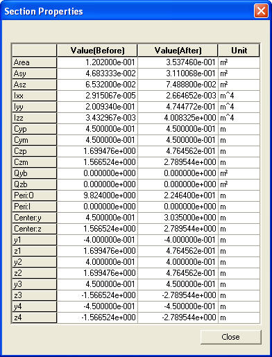
Click
![]() to display the section
property data. The section property data table is either calculated
from the main dimensions or obtained from the DB depending on
the method of data entry. [Details]
to display the section
property data. The section property data table is either calculated
from the main dimensions or obtained from the DB depending on
the method of data entry. [Details]
Area: Cross sectional area
Asy: Effective Shear Area for shear force in the element's local y-direction
It becomes inactive when Shear Deformation is not considered.
Asz: Effective Shear Area for shear force in the element's local z-direction
It becomes inactive when Shear Deformation is not considered.
Ixx: Torsional constant about the element's local x-axis
Iyy: Moment of Inertia about the element's local y-direction
Izz: Moment of Inertia about the element's local z-direction
Cyp: Distance from the section's neutral axis to the extreme fiber of the element in the local (+)y-direction
Cym: Distance from the section's neutral axis to the extreme fiber of the element in the local (-)y-direction
Czp: Distance from the section's neutral axis to the extreme fiber of the element in the local (+)z-direction
Czm: Distance from the section's neutral axis to the extreme fiber of the element in the local (-)z-direction
Qyb: Shear Coefficient for the shear force applied in the element's local z-direction
Qzb: Shear Coefficient for the shear force applied in the element's local y-direction
Peri: O: Total perimeter of the section
Peri: I: Inside perimeter length of a hollow section
y1, z1: Distance from the section's neutral axis to the Location 1 (used for computing combined stress)
y2, z2: Distance from the section's neutral axis to the Location 2 (used for computing combined stress)
y3, z3: Distance from the section's neutral axis to the Location 3 (used for computing combined stress)
y4, z4: Distance from the section's neutral axis to the Location 4 (used for computing combined stress)
Zyy: Plastic Section Modulus about the element local y-direction
Zzz: Plastic Section Modulus about the element local z-direction
Iw: Warping constant
w1, w2, w3 and w4: Warping function at point 1, 2, 3 and 4 respectively
Cxy1, Cxy2, Cxy3, Cxy4, Cxz1, Cxz2, Cxz3 and Cxz4: Coefficients to be used to calculate twisting moment and warping moment

ys-yc: Distance between centroid and shear center in the local y direction
zs-zc: Distance between centroid and shear center in the local z direction
Ip: Polar moment of inertia
Note 1
All the above section property data except for Area and Peri are required for beam elements.
Note 2
The shear deformations are neglected if the effective shear areas are not specified. Cyp, Cym, Czp and Czm are used to calculate the bending stresses. Qyb and Qzb are used to calculate the shear stresses. Peri is used to calculate the Painting Area.
Note 3
Zyy and Zzz are used to calculate the strength for pushover analysis when Value Type Steel Section has been assigned Design > Pushover Analysis > Define Hinge Properties.
Note 4 Element Stiffness data
Sections can be defined by the stiffness data entries even though the section dimensions (H, B1, ... , etc.) are not entered.
The cross-sectional area of a member is used to compute axial stiffness and stress when the member is subjected to a compression or tension force. Figure 1 illustrates the calculation procedure.
Cross-sectional areas could be reduced due to member openings and bolt or rivet holes for connections. MIDAS/Civil does not consider such reductions. Therefore, if necessary, the user is required to modify the values using the option 2 above and his/her judgment.
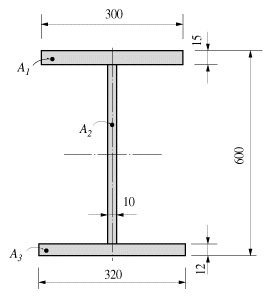
Area = +dA = A1 + A2 + A3
= (300 x 15) + (573 x 10) + (320 x 12)
= 14070
<Figure 1> Example of cross-sectional area calculation
Effective Shear Areas (Asy, Asz)
The effective shear areas of a member are used to formulate the shear stiffness in the y- and z-axis directions of the cross-section. If the effective shear areas are omitted, the shear deformations in the corresponding directions are neglected.
When MIDAS/Civil computes the section properties by the option 1 or 3, the corresponding shear stiffness components are automatically calculated. Figure 2 outlines the calculation methods.
Asy: Effective shear area in the ECS y-axis direction
Asz: Effective shear area in the ECS z-axis direction
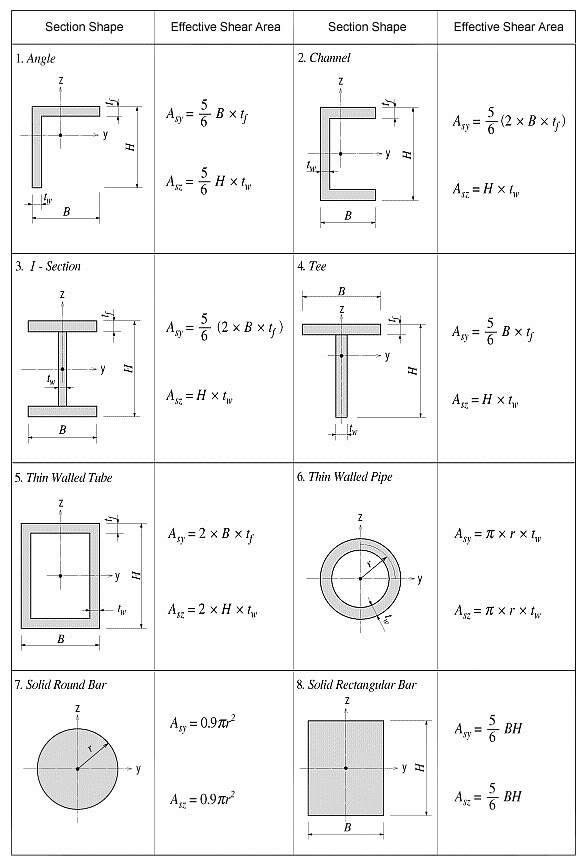
<Figure 2> Effective Shear Area calculations
Torsional resistance refers to the stiffness resisting torsional moments. It is expressed as
<Eq. 1>
![]()
where,
Ixx: Torsional Constant
T: Torsional moment or torque
G: Shear Modulus of Elasticity
θ : Angle of twist
The torsional stiffness expressed in Eq. 1 must not be confused with the polar moment of inertia that determines the torsional shear stresses. However, they are identical to one another in the cases of circular or thick cylindrical sections.
No general equation exists to satisfactorily calculate the torsional resistance applicable for all section types. The calculation methods widely vary for open and closed sections and thin and thick thickness sections.
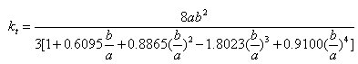
For calculating the torsional resistance of an open section, an approximate method is used; the section is divided into several rectangular sub-sections and then their resistances are summed into a total resistance, Ixx, calculated by the equation below.
<Eq. 2>
![]()
.gif)
for a e b
where,
Ixx: Torsional resistance of a (rectangular) sub-section
2a: Length of the longer side of a sub-section
2b: Length of the shorter side of a sub-section
Figure 3 illustrates the equation for calculating the torsional resistance of a thin walled, tube-shaped, closed section.
<Eq. 3>
.gif)
where,
A: Area enclosed by the mid-line of the tube
ds: Infinitesimal length of thickness centerline at a given point
t: Thickness of tube at a given point
For those sections such as bridge box girders, which retain the form of thick walled tubes, the torsional stiffness can be obtained by combining the above two equations, Eq. 1 and Eq. 3.
Torsional
resistance: .gif)
Shear stress at a given point: .gif)
Thickness of tube at a given point:![]()
<Figure 3> Torsional resistance of a thin walled, tube-shaped, closed section
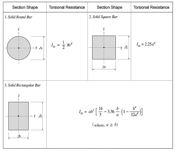
<Figure 4> Torsional resistance of solid sections
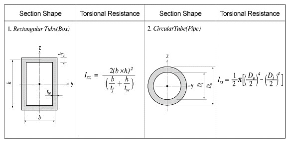
<Figure 5> Torsional resistance of thin walled, closed sections
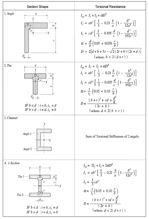
<Figure 6> Torsional resistance of thick walled, open sections
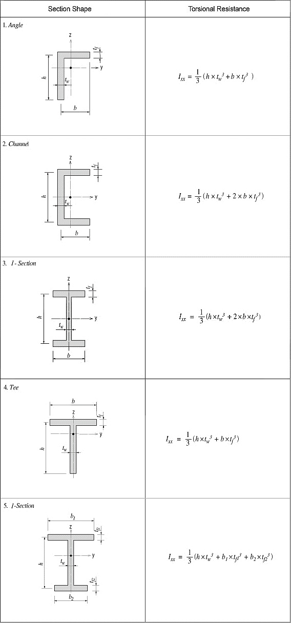
<Figure 7> Torsional resistance of thin walled, open sections
In practice, combined sections often exist. A combined built-up section may include both closed and open sections. In such a case, the stiffness calculation is performed for each part, and their torsional stiffnesses are summed to establish the total stiffness for the built-up section.
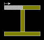
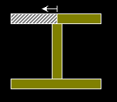
For example, a double I-section shown in Figure 8(a) consists of a closed section in the middle and two open sections, one on each side.
The torsional resistance of the closed section (hatched part)
<Eq. 4>
.gif)
The torsional resistance of the open sections (unhatched parts)
<Eq. 5>
.gif)
The total resistance of the built-up section
<Eq. 6>
![]()
Figure 8(b) shows a built-up section made up of an I-shaped section reinforced with two web plates, forming two closed sections. In this case, the torsional resistance for the section is computed as follows:
If the torsional resistance contributed by the flange tips is negligible relative to the total section, the torsional property may be calculated solely on the basis of the outer closed section (hatched section) as expressed in Eq. 7.
<Eq. 7>
.gif)
If the torsional resistance of the open sections is too large to ignore, then it should be included in the total resistance.
(a) Section consisted of closed and open sections
(b) Section consisted of two closed sections
<Figure 8> Torsional resistance of built-up sections
Area Moment of Inertia (Iyy, Izz)
The area moment of inertia is used to compute the flexural stiffness resisting bending moments. It is calculated relative to the centroid of the section.
Area moment of inertia about the ECS y-axis
<Eq. 8>
![]()
-Area moment of inertia about the ECS z-axis
<Eq. 9>
![]()
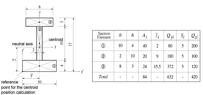
![]() : area
: area
![]() : distance from the reference point to the centroid of the
section element in the z-axis direction
: distance from the reference point to the centroid of the
section element in the z-axis direction
![]() : distance from the reference point to the centroid of the
section element in the y-axis direction
: distance from the reference point to the centroid of the
section element in the y-axis direction
![]() : first moment of area relative to the reference point in
the y-axis direction
: first moment of area relative to the reference point in
the y-axis direction
![]() : first moment of area relative to the reference point in
the z-axis direction
: first moment of area relative to the reference point in
the z-axis direction
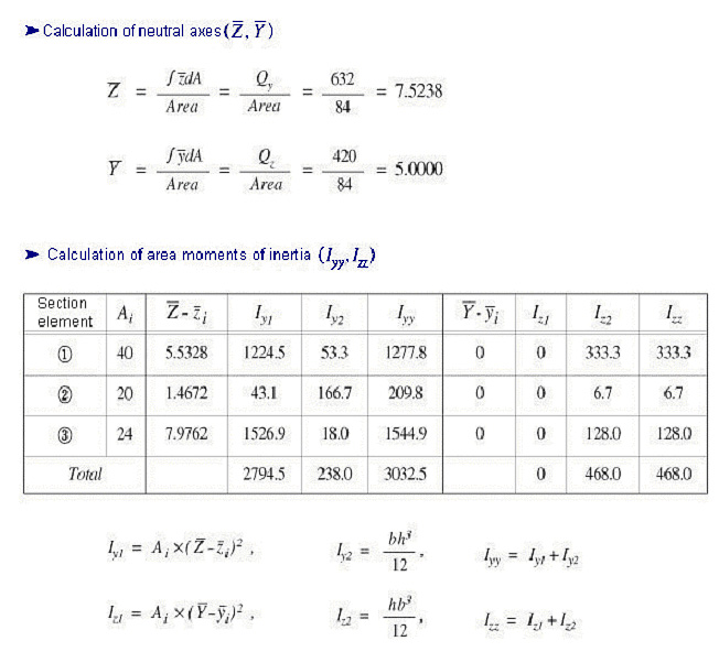
<Figure 9> Example of calculating area moments of inertia
Area Product Moment of Inertia (Iyz)
The area product moment of inertia is used to compute stresses for non-symmetrical sections, which is defined as follows:
<Eq. 10>
![]()
Sections that have at least one axis of symmetry produce Iyz=0. Typical symmetrical sections include I, pipe, box, channel and tee shapes, which are symmetrical about at least one of their local axes, y and z. However, for non-symmetrical sections such as angle shaped sections, where Iyz`0, the area product moment of inertia should be considered for obtaining stress components.
The area product moment of inertia for an angle is calculated as shown in Figure 10.
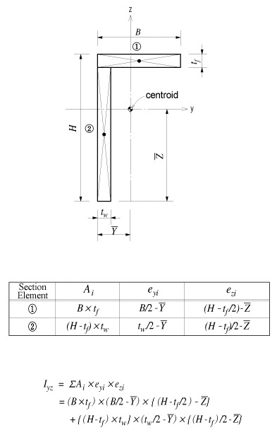
<Figure 10> Area product moment of inertia for an angle
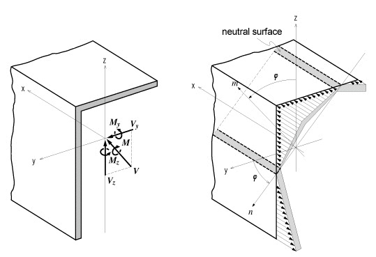
<Figure 11> Bending stress distribution of a non-symmetrical section
The neutral axis represents an axis along which bending stress is 0 (zero). As illustrated in the right-hand side of Figure 11, the n-axis represents the neutral axis, to which the m-axis is perpendicular. Since the bending stress is zero at the neutral axis, the direction of the neutral axis can be obtained from the relation defined as
<Eq. 11>
![]()
.gif)
The following represents a general equation applied to calculate the bending stress of a section:
<Eq. 12>
.gif)
In the case of an I shaped section, Iyz=0, hence the equation can be simplified as:
<Eq. 13>
.gif)
where,
Iyy: Area moment of inertia about the ECS y-axis
Izz: Area moment of inertia about the ECS z-axis
Iyz: Area product moment of inertia
y: Distance from the neutral axis to the location of bending stress calculation in the ECS y-axis direction
z: Distance from the neutral axis to the location of bending stress calculation in the ECS z-axis direction
My: Bending moment about the ECS y-axis
Mz: Bending moment about the ECS z-axis
The general expressions for calculating shear stresses in the ECS y and z-axes are:
<Eq. 14>
.gif)
<Eq. 15>
.gif)
where,
Vy: Shear force in the ECS y-axis direction
Vz: Shear force in the ECS z-axis direction
Qy: First moment of area about the ECS y-axis
Qz: First moment of area about the ECS z-axis
by: Thickness of the section at which a shear stress is calculated, in the direction normal to the ECS z-axis
bz: Thickness of the section at which a shear stress is calculated, in the direction normal to the ECS y-axis
The first moment of area is used to compute the shear stress at a particular point on a section. It is defined as follows:
<Eq. 16>
![]()
<Eq. 17>
![]()
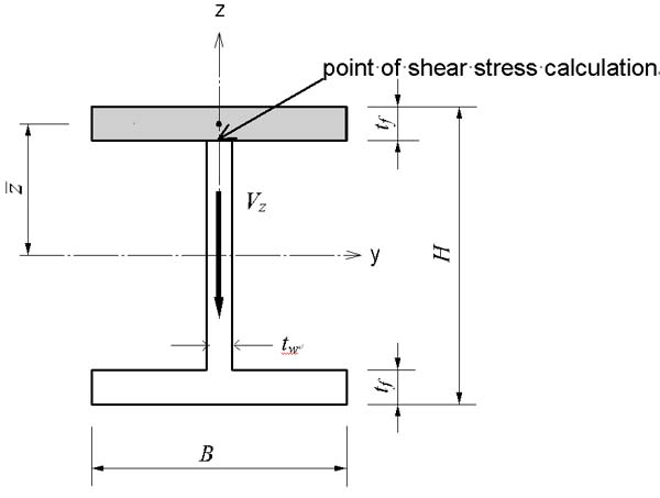
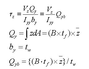
When a section is symmetrical about at least one of the y and z-axis, the shear stresses at a particular point are:
<Eq. 18>
.gif)
<Eq. 19>
.gif)
where,
Vy: Shear force acting in the ECS y-axis direction
Vz: Shear force acting in the ECS z-axis direction
Iyy: Area moment of inertia about the ECS y-axis
Izz: Area moment of inertia about the ECS z-axis
by: Thickness of the section at the point of shear stress calculation in the ECS y-axis direction
bz: Thickness of the section at the point of shear stress calculation in the ECS z-axis direction
Shear Factor for Shear Stress (Qyb, Qzb)
The shear factor is used to compute the shear stress at a particular point on a section, which is obtained by dividing the first moment of area by the thickness of the section.
<Eq. 20>
.gif) ,
, .gif)
<Eq. 21>
.gif) ,
, .gif)
<Figure 12> Example of calculating a shear factor
Stiffness of Composite Sections
midas Civil calculates the stiffness for a full composite action of structural steel and reinforced concrete. Reinforcing bars are presumed to be included in the concrete section. The composite action is transformed into equivalent section properties.
The program uses the elastic moduli of the steel (Es) and concrete (Ec) defined in the SSRC79 (Structural Stability Research Council, 1979, USA) for calculating the equivalent section properties. In addition, the Ec value is decreased by 20% in accordance with the EUROCODE 4.
- Equivalent cross-sectional area
.gif)
- Equivalent effective shear area
.gif)
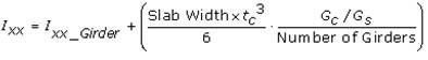
- Equivalent area moment of inertia
.gif)
where,
Ast1: Area of structural steel
Acon: Area of concrete
Asst1: Effective shear area of structural steel
Ascon: Effective shear area of concrete
Ist1: Area moment of inertia of structural steel
Icon: Area moment of inertia of concrete
REN: Modular ratio (elasticity modular ratio of the structural steel to the concrete, Es/Ec)
![]() Revision
of Ver.7.4.0
Revision
of Ver.7.4.0
- Equivalent torsional coefficient
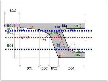
Note 5 Determining the positions of y1~4, z1~4 of a section imported from SPC [Details]
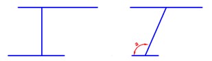
1. Divide the section into four quadrants.
2. Assign the positions furthermost from the centroid in each quadrant for checking stresses.
If the webs of a section are extensively sloped as in the above diagram, the points furthermost from the centroid may not be the lowest points of the section. Use caution that the stress checking positions of quadrants 3 & 4 may be selected differently from the expectation.
 Section Type
DB/User tab
The section data can be entered by the following 2 methods in the dialog box:
1. Select a section from the DB (database) of the standard sections for a country.
2. Enter the main dimensions of a standardized section shape.
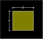
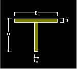
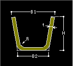
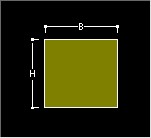
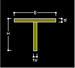
Section Shape List: Select a section shape (Angle, Channel, H-Section, T-Section, Box, Pipe, Double Angle, Double Channel, Solid Rectangle, Solid Round, Octagon, Solid Octagon, R-Octagon, Track, Solid Track, Half Track, Cold Formed Channel & U-Rib).
User: Enter the main dimensions of a standardized section shape.
H, B1, ...: Refer to the dimension information diagram in the dialog box.
DB: Select a section from the DB of the standard sections for a country.
AISC2K(US): American Institute of Steel Construction, 2000 US Unit : lb, in
AISC2K(SI): American Institute of Steel Construction, 2000 SI Unit : kN, m, mm
AISC: American Institute of Steel Construction
CISC02(US): Canadian Institute of Steel Construction (US Unit : lb, in)
CISC02(SI): Canadian Institute of Steel Construction (SI Unit : kN, m, mm)
BS(S): British Standard
Note
BS indicates BS4-1 revised prior to 1993.
BS4 - 93: British Standard / BS 4-1 : 1993
DIN(S): Deutches Institut fur Normung e.v
UNI: Italian National Standard
GOST: Russian National Standard
STO_ASChM: Russian National Standard
JIS2K : Japanese Industrial Standards 2000
JIS: Japanese Industrial Standards
KS: Korean Industrial Standards
GB-YB: Guojia Biao Zhun-Yejin Bu Biao Zhun
Pacific(SI): Bentley Pacific Standards (SI Unit : kN, m, mm)
IS84: Indian Standards
GB-YB05: Guojia Biao Zhun-Yejin Bu Biao Zhun(2005)
CNS91: Taiwan Standards
Sect. Name: Enter directly a DB section name or select a desired DB from the Section list. When the section name is directly entered, it must correspond to the format of the DB section names.
Ex) AISC: W36x280, BS: UB 406x178x54, DIN: HD400x288
Note
When specifying Double Angle or Double Channel sections, assign the sectional shape in the list and select User. Then, select DB and Sect. Name from Get Data from Single Angle (or Channel) or directly enter the main dimensions of the section.
Value tab
The section data can be entered by the following 3 methods in the dialog box:
1. Select a section from the DB (database) of the standard sections for a country.
2. Enter the main dimensions of a standardized section shape.
3. Import a section generated from SPC module.
Section Shape List: Assign a section shape to use.
Built-Up Section: Fabricated section
Note
Check '.jpg) ' in the
case of a built-up section and leave it blank in the case
of a rolled steel section. The data is referred to for
strength verification for steel members and compiling
material quantities in BOM.
' in the
case of a built-up section and leave it blank in the case
of a rolled steel section. The data is referred to for
strength verification for steel members and compiling
material quantities in BOM.Size
H, B1, ...: Refer to the diagram denoting section dimensions in the dialog box.
The structure can be analyzed only with the stiffness data even if the section dimensions are not specified.
Section Properties
The main section dimensions entered in Size are used to calculate and display the section stiffness.
Area: Cross sectional area
Asy: Effective Shear Area for shear force in the element's local y-direction
It becomes inactive when Shear Deformation is not considered.
Asz: Effective Shear Area for shear force in the element's local z-direction
It becomes inactive when Shear Deformation is not considered.
Ixx: Torsional Resistance about the element's local x-axis
Iyy: Moment of Inertia about the element's local y-direction
Izz: Moment of Inertia about the element's local z-direction
Cyp: Distance from the section's neutral axis to the extreme fiber of the element in the local (+)y-direction
Cym: Distance from the section's neutral axis to the extreme fiber of the element in the local (-)y-direction
Czp: Distance from the section's neutral axis to the extreme fiber of the element in the local (+)z-direction
Czm: Distance from the section's neutral axis to the extreme fiber of the element in the local (-)z-direction
Qyb: Shear Coefficient for the shear force applied in the element's local z-direction
Qzb: Shear Coefficient for the shear force applied in the element's local y-direction
Peri:O: Total perimeter of the section
Peri:I: Inside perimeter length of a hollow section
Note
The value of Peri:I is '0' for an I-shaped section since the section is not hollow.Cent:y: Centroidal distance in ECS y-axis
Cent:z: Centroidal distance in ECS z-axis
y1, z1: Distance from the section's neutral axis to the Location 1 (used for computing combined stress) The user may specify the location of the stress display.
y2, z2: Distance from the section's neutral axis to the Location 2 (used for computing combined stress) The user may specify the location of the stress display.
y3, z3: Distance from the section's neutral axis to the Location 3 (used for computing combined stress) The user may specify the location of the stress display.
y4, z4: Distance from the section's neutral axis to the Location 4 (used for computing combined stress) The user may specify the location of the stress display.
Zyy: Plastic Section Modulus about the element local y-direction
Zzz: Plastic Section Modulus about the element local z-direction
SRC tab
Enter the section property data for steel RC composite members in the dialog box.
Shape: Assign a section shape to use.
Note
New Cross I Section and Combined T-Section were incorporated.Concrete Data: Enter the outer dimensions of the RC section of a steel-encased concrete section.
Steel Data: Enter the steel section data.
User: Enter the main dimensions of a standardized section shape.
H, B1, ...: Refer to the dimension information diagram in the dialog box.
DB: Select a section from the DB of the standard sections for a country.
AISC2K(US): American Institute of Steel Construction, 2000 US Unit : lb, in
AISC2K(SI): American Institute of Steel Construction, 2000 SI Unit : kN, m, mm
AISC: American Institute of Steel Construction
CISC02(US): Canadian Institute of Steel Construction (US Unit : lb, in)
CISC02(SI): Canadian Institute of Steel Construction (SI Unit : kN, m, mm)
BS(S): British Standard
Note
BS indicates BS4-1 revised prior to 1993.
BS4 - 93: British Standard / BS 4-1 : 1993
DIN(S): Deutches Institut fur Normung e.v
JIS2K : Japanese Industrial Standards 2000
JIS: Japanese Industrial Standards
KS: Korean Industrial Standards
GB-YB: Guojia Biao Zhun-Yejin Bu Biao Zhun
Pacific(SI): Bentley Pacific Standards (SI Unit : kN, m, mm)
IS84: Indian Standards
CNS91: Taiwan Standards
Steel Name: Enter directly a DB section name or select a desired DB from the Section list. When the section name is directly entered, it must correspond to the format of the DB section names.
Ex) AISC: W36x280, BS: UB 406x178x54, DIN: HD400x288, JIS, KS: H 400x200x8/13
Material: Enter material properties for steel and concrete constituting steel RC composite sections.
Click
.jpg) to select
the material properties for steel and concrete stored
in the DB for a country. The following items are automatically
entered:
to select
the material properties for steel and concrete stored
in the DB for a country. The following items are automatically
entered:Es/Ec: Modulus of Elasticity Ratio of steel relative to concrete
Ds/Dc: Specific Weight (Density) Ratio of steel relative to concrete
Ps: Poisson's Ratio for steel
Pc: Poisson's Ratio for concrete
Combined Ratio of Conv.: Stiffness Reduction Factor of concrete [Default = 1.0]
Note
When RC is converted into steel for calculating the SRC section stiffness, Conv. Stiffness Factor is applied to reduce the stiffness of RC.Replace: Assign Steel to be the reference when calculating stiffness of a composite section
Note
midas Civil converts RC into equivalent steel for SRC section stiffness calculation.
Combined tab
In this dialog box, enter the section properties for a combined section made up by two standard section types.
User: Enter the main dimensions of standardized section shapes.
DB: Select the sections from the DB of the standard sections for a country.
AISC2K(US): American Institute of Steel Construction, 2000 US Unit : lb, in
AISC2K(SI): American Institute of Steel Construction, 2000 SI Unit : kN, m, mm
AISC: American Institute of Steel Construction
CISC02(US): Canadian Institute of Steel Construction (US Unit : lb, in)
CISC02(SI): Canadian Institute of Steel Construction (SI Unit : kN, m, mm)
BS(S): British Standard
Note
BS indicates BS4-1 revised prior to 1993.
BS4 - 93: British Standard / BS 4-1 : 1993
DIN(S): Deutches Institut fur Normung e.v
JIS2K : Japanese Industrial Standards 2000
JIS: Japanese Industrial Standards
KS: Korean Industrial Standards
GB-YB: Guojia Biao Zhun-Yejin Bu Biao Zhun
Pacific(SI): Bentley Pacific Standards (SI Unit : kN, m, mm)
IS84: Indian Standards
CNS91: Taiwan Standards
Data 1, Data 2: Enter the section data for individual components constituting the combined section.
Sect. Name: Enter directly a DB section name or select a desired DB from the Section list. When the section name is directly entered, it must correspond to the format of the DB section names.
Ex) AISC: W36x280, BS: UB 406x178x54, DIN: HD400x288, JIS, KS: H 400x200x8/13
H, B, ...: Refer to the diagram denoting section dimensions in the dialog box.
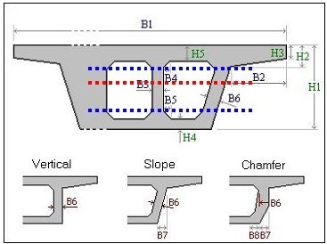
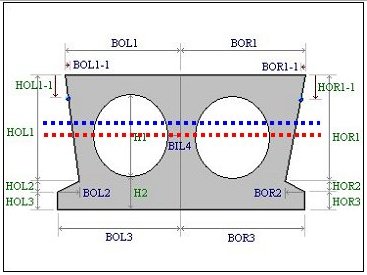
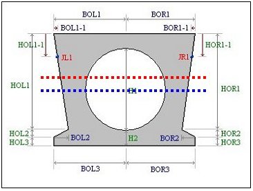
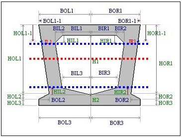
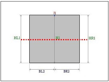
PSC tab
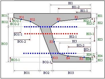
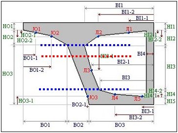
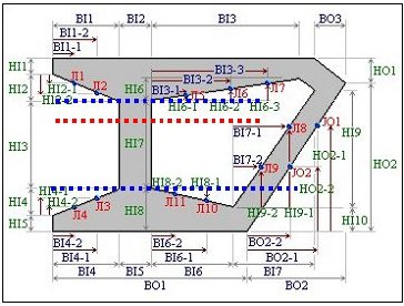
In this dialog box, enter the section property data for prestressed concrete members. PSC (Post-tensioned Concrete) Section can be defined in a variety of shapes (PSC-Normal, 1Cell/2Cell, 3Cell, nCell, Mid, I, Half, Tee & Plat).
Joint on/off
Check on the joint numbers to activate the entry fields to additionally define the variant dimensions of the section.JO1, JO2, JO3: Selectively check on the points in the Outer tab referring to the guide diagram.
JI1, JI2, ..., JI5: Selectively check on the points in the Inner tab referring to the guide diagram.
Section Type: Assign the number of internal compartments of the section.
1 Cell: single cell
2 Cell: double cell
Shear Check: Check shear stresses at Z1, Z2 and Z3 locations. Z1 and Z3 can be either input directly by the user or specified automatically. If the Auto option is checked, the program checks shear at the top and bottom ends of the webs.
Z1: Distance from the centroid to the underside of the top flange at the webs
Z3: Distance from the centroid to the upperside of the bottom flange at the webs
Note
If the "AUTO" option is checked, the program automatically checks the shear at the following locations depending upon the PSC section shapes. [Details]
PSC - 1CELL PSC - 2CELL
PSC - 3CELL PSC - nCELL
PSC - I PSC - TEE
PSC - PLAT
Section Type : Half Section Type : 2CELL
Section Type : 1CELL(Type = Circle) Section Type : 1CELL(Type = Polygon)
PSC - MID
Cell Type : None Cell Type : Circle
PSC - HALF
Cell Type : None Cell Type : Circle
PSC - nCELL2
Cell Type : Polygon(Cell Num=1) Cell Type : Polygon(Cell Num=1)
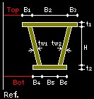
Web Thick
Shear forces are calculated at the parts critical to shear in the PSC section. The user can directly enter the position. If the Auto option is checked on, the program checks shear at the top and bottom ends of the webs (Z1 and Z3 in the PSC Viewer dialog).
for Shear (total): Sum of web thicknesses at Z1, Z2 and Z3 for shear stress checks, which can be specified different from actual thicknesses. Checking on Auto uses the true web thicknesses.
- t1: Sum of web thicknesses at Z1 for shear stress check
- t2: Sum of web thicknesses at Z2 for shear stress check
- t3: Sum of web thicknesses at Z3 for shear stress check
for Torsion (min.): Minimum web thickness for torsional stress can be entered by the user or specified automatically.
Mesh Size for Sitff. Calc.: Enter mesh size for computing the stiffness of PSC section.
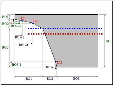
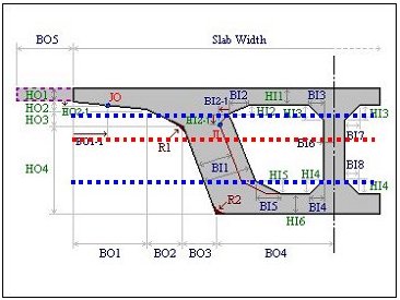
Outer: Outer dimensions
HO1, HO2, ...: Enter the dimensions referring to the guide diagram on the left side of the dialog box.
Inner: Inner dimensions
HI1, HI2, ...: Enter the dimensions referring to the guide diagram on the left side of the dialog box.
 :Input
PSC section data in a table. It is convenient to input
the data in a spreadsheet format since there are many
items to input. Section data that is frequently used can
be saved as an Excel data for later use.
:Input
PSC section data in a table. It is convenient to input
the data in a spreadsheet format since there are many
items to input. Section data that is frequently used can
be saved as an Excel data for later use.Click
 to display the centroid of the
section.
to display the centroid of the
section.PSC Viewer: Display the section to a true scale based on the dimensions and the section shape.
PSC Section Type
Normal 1Cell , 2Cell PSC Box section
Default: Enter the basic dimensions of the 3 cell PSC Box.
Option: Enter the dimension of the joints which is checked at the Joint On/Off.
Type: Assign the type of the web of a PSC Box Section (Refer to PSC Viewer)
Size: Enter the size of a PSC Box Section.
Num. of Cell: Number of Cells
Symmetry: Select whether the section is symmetrical or not. Unchecking this option will activate the Right entry field.
Cell Type: Select the shape of cell
Polygon
Circle
Side Hole: Select whether to include a circular hole or not.
Left Side: The shape of left-side PSC Section
Right Side: The shape of right-side PSC Section (activated if unsymmetrical)
Symmetry: Select whether the section is symmetrical or not. Unchecking this option will activate the Right entry field.
Cell Type
Left : Select the desired section shape among the None, Circle and Polygon.
Note
To calculate Ixx of a PSC section, use the least value of flange thickness considering the haunch.For the sloped upper flange,
.jpg)
Here, Am, ts and ds represent the closed sectional area, the least thickness and the section length respectively.
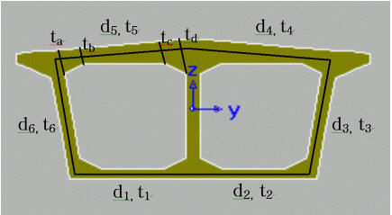
t1~t6 are the least thickness, and the upper flange thickness (ta and t5) will be determined by the least thickness among ta~td.
d1~d6 represent the length of each side. Am represents the closed area, bounded by the lines that run parallel to the outer lines of the section and pass through the center points of the least thicknesses.
Symmetry: Select whether the section is symmetric or not. Unchecking this option will activate the Right entry field.
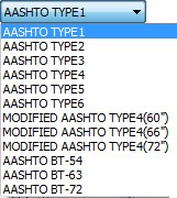
Section Name
The user can manually specify the section dimensions by selecting "None" or select one of the sections in the built-in database for the AASHTO and several DOT standard sections. Those DOTs are: Caltrans, Iowa DOT, Missouri DOT, Ohio DOT, Texas DOT, Virginia DOT, and Wisconsin DOT.
When AASHTO or one of the DOT is selected, the corresponding standard sections are listed as shown below:
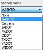
AASHTO
Caltrans
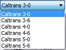
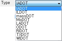
IADOT
MoDOT
ODOT
TXDOT
VADOT
WIDOT
Cell Type
Left: Select the desired section shape among the None, Circle and Polygon.
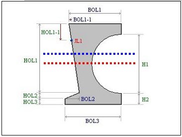
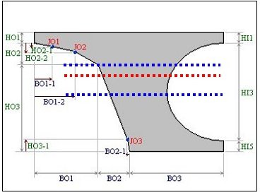
Outer: Outer dimensions
HO1, HO2, ...: Enter the dimensions referring to the guide diagram on the left side of the dialog box.
Inner: Inner dimensions
HI1, HI2, ...: Enter the dimensions referring to the guide diagram on the left side of the dialog box.
Note
When a multi-cell PSC Box is modeled using a grid model, it will be easier to use PSC-Half for the exterior section and PSC-Mid for the interior section.T type PSC beam section
Section with a hollow core in the shape of a circle or polygon
Section Type: Select among the Half, 1 Cell and 2 Cell types.
Half: Select Left or Right.
1Cell: Select Circle or Polygon.
2Cell: Select to enter a 2 Cell section with circular shaped hollow cores.
 :Define the PSC section by inputting
its coordinates.
:Define the PSC section by inputting
its coordinates.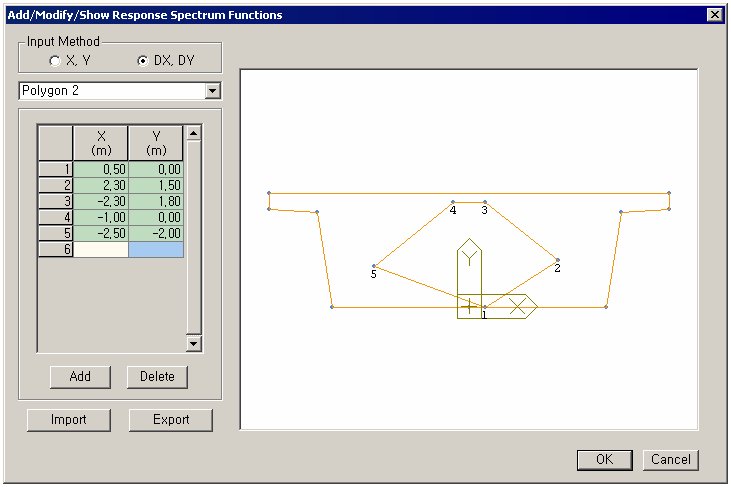
Input Method
X, Y: Define the Polygon by inputting the absolute coordinates.
DX, DY: Enter the increment from the point on the Polygon to define the coordinates.
Add: Complete the Polygon with the coordinates inputted.
Delete: Delete the polygon selected from the list.
Import: Import the predefined section data (*.uds).
Export: Export the define section data to a file (*.uds)
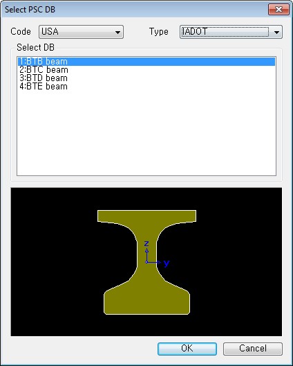
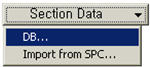 DB:
PSC Section Data Base for UK, Italy, USA, AS, NZ and
Russia
DB:
PSC Section Data Base for UK, Italy, USA, AS, NZ and
Russia
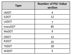
The standard sections of several DOTs are implemented in the PSC database under USA option.
Those DOTs are Iowa DOT (IADOT), Illinois DOT (ILDOT), Massachusetts DOT (massDOT), Louisiana DOT (LADOT), Ohio DOT (ODOT), Rhode Island DOT (RIDOT), Texas DOT (TXDOT), and Wisconsin DOT (WIDOT).
For each DOT type selected, the corresponding sections are listed under the 'Select DB' box.
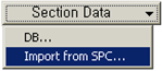 Import
from SPC: Import section data (*.sec file)
generated from SPC (Section Property Calculator).
Section properties and shape are then automatically
entered. In order to import a specific section in
Civil, the user must save the file in the *.sec format
in SPC.
Import
from SPC: Import section data (*.sec file)
generated from SPC (Section Property Calculator).
Section properties and shape are then automatically
entered. In order to import a specific section in
Civil, the user must save the file in the *.sec format
in SPC.Param. for Design: Enter the section dimensions to be used for design, referring to PSC Viewer. The dimensions are used for calculating the shear strength. If 0 is inputted in T2, then the program automatically recognizes the section as a Tee section, and uses BT as web thickness. The parameters for closed section and open section are calculated using the following equations:
Input method of section dimension for design by section types [Details]
1) Box section (Closed type): Refer to the PSC Viewer Dialog.
2) T section (Open type): For design of T- section, specify 0 for T2.
Web thickness is specified by 'Thk. for Torsion(min.)', and flange width is specified by the distance between y1 and y2 of Section Properties. That is, BT does not affect
3) I section (Open type): For design of I-section, specify 0 for BT
Thicknesses of the top and bottom flanges are specified by T1 and T2 respectively. Web thickness is specified by Thk. for Torsion(min.).
Widths of the top and bottom flanges are specified by the distance from y1 to y2 and from y3 to y4 respectively.
For closed section:

For open section:

Where, F = the area enclosed by the centerlines of the plates of the closed section, t = the thickness of the plate
For Chinese Design Spec. Roark's Formula is used:
Thk. for Torsion (min.): Enter the minimum web thickness for calculating torsional stress.
Shear Check: Check shear stresses at Z1, Z2 and Z3 locations. Enter Z1 and Z3 directly. Qy and Thk for Shear (total)"can be either directly inputted by the user or specified automatically.
Note
Refer to "Calculation of arbitrary section form using SPC" for a detailed explanation.
PSC Section with corrugated steel web
Symmetric
Haunch: Section with haunch
CMP: Enter the dimensions for corrugated steel web, referring to the guide diagram.
E.F.D.: End Fixity degree (
 ). Factor to calculate design buckling stiffness.
L.R.F.: Length Reduction Factor (
 ).
Factor to calculate design buckling stiffness.
).
Factor to calculate design buckling stiffness.
Material
Es/Ec: Enter ratio of elastic modulus of steel to concrete.
Ds/Dc: Enter ratio of density of steel to concrete.
Ps: Enter Poisson's Ratio of steel.
Pc: Enter Poisson's Ratio of concrete.
Note
The maximum number of voids that can be created is 21.
Tapered tab
In this dialog box, enter the section properties for both ends of a line element to define a non-uniform section (Non-prismatic Section/ Tapered Section) of identical shape.(Refer to Note)
Section Shape List: Applicable tapered section shapes are shown below. For PSC, Composite Type or General Section of Value type, pre-defined sections can be brought in from the Section DB.
DB/User: All sections except for the R-Octagon section

Value: All sections except for the R-Octagon section

PSC: All PSC Type sections

Composite: Composite sections (Steel-Box, Steel-I, PSC-I, PSC-T & General section)
Value: Assign value when the user directly enters the section stiffness data.
Enter the section dimensions for section-i and j separately and click
.jpg) .
Then, the user may modify the auto-calculated stiffness
data or directly enter the stiffness data without entering
the section dimensions.
.
Then, the user may modify the auto-calculated stiffness
data or directly enter the stiffness data without entering
the section dimensions.User: Enter the main dimensions of standardized section shapes.
DB: Select the sections from the DB of the standard sections for a country.
AISC2K(US): American Institute of Steel Construction, 2000 US Unit : lb, in
AISC2K(SI): American Institute of Steel Construction, 2000 SI Unit : kN, m, mm
AISC: American Institute of Steel Construction
CISC02(US): Canadian Institute of Steel Construction (US Unit : lb, in)
CISC02(SI): Canadian Institute of Steel Construction (SI Unit : kN, m, mm)
BS(S): British Standard
DIN(S): Deutches Institut fur Normung e.v
JIS2K : Japanese Industrial Standards 2000
JIS: Japanese Industrial Standards
KS: Korean Industrial Standards
GB-YB: Guojia Biao Zhun-Yejin Bu Biao Zhun
Pacific(SI): Bentley Pacific Standards (SI Unit : kN, m, mm)
IS84: Indian Standards
CNS91: Taiwan Standards
Section-i, Section-j: Enter directly each section name corresponding to the starting section-i and the ending section-j or select the desired DB from the section list to describe the tapered section. When the section names are directly entered, they must correspond to the DB section name format.
Ex) AISC: W36x280, BS: UB 406x178x54, DIN: HD400x288, JIS, KS: H 400x200x8/13
y Axis Variation: Dimensional variation affects the moment of inertia about the element local y-axis along the length.
z Axis Variation: Dimensional variation affects the moment of inertia about the element local z-axis along the length.
Linear: linear variation along the element local x-direction
Parabolic: parabolic variation along the element local x-direction
Cubic: cubic variation along the element local x-direction
Note 1
Calculation of section properties as per Dimensional Variation [Details]
Once the main section dimensions of both ends of a tapered section member are entered, the section properties are considered to vary from the i end (element connection node N1) to the j end (element connection node N2) along the member length. The cross sectional areas, effective shear areas and torsional resistances are assumed to vary linearly from i to j along the element local x-axis. The moments of inertia are assumed to vary linearly, parabolically or cubically depending on the directions of section changes.
For instance, in the figures below, the variations of Iyy and Izz can be expressed as follows:
Moments of Inertia about strong and weak axes for a rectangular section <See figure below>
.jpg)
.jpg)
When the width (B) is constant and the height (H) varies, the moments of inertia show a cubic variation about the strong axis and a linear variation about the weak axis. Namely, Iyy Variation = 'Cubic', Izz Variation = 'Linear'.
Moments of Inertia about strong and weak axes for an I-section <See figure below>
.jpg)
.jpg)
When the width (B) is constant and the height (H) varies, the moment of inertia about the strong axis shows a nearly parabolic variation if the 1st and 2nd terms are neglected in the above equation. The moment of inertia about the weak axis varies almost linearly. Hence, it is feasible to use Iyy Variation = 'Parabolic', Izz Variation = 'Linear'. On the other hand, when the height (H) is constant and the width (B) varies, the moment of inertia about the strong axis varies almost linearly and the moment of inertia about the weak axis shows a nearly cubic variation. Hence, it is feasible to use Iyy Variation = 'Linear', Izz Variation = 'Cubic'.
.jpg)
Entry of section data for a tapered section member
Note 2
In the results produced in contours, diagrams and tables, dimensional variation in the axial direction affects the moment of inertia only. In Beam Detail Analysis, section properties are directly calculated at 1/4, 1/2 and 3/4 points using the shape information. As such, dimensional variation affects all the section properties (A, Asy, Asz, Ixx, Iyy & Izz).
Composite tab
In this dialog box, the sectional data pertaining to the "Analysis considering the section variation before and after composite actions in Composite Bridges" are specified.
Section Type: Assign a section type
Composite-T Steel-Box Steel-I Composite-I Composite-Tub
Steel-Box (Type 1): Structural steel Box Shape Girder
Steel -I (Type 1): Structural Steel I Shape Girder
Steel -I (Type 2): Structural Steel I Shape Girder. Asymmetric section can be defined.
-1.png)
-2.png)
Steel -Tub (Type 1): Structural Steel Tub Shape Girder
Steel -Tub (Type 1): Structural Steel Tub Shape Girder. Asymmetric section can be defined.
Composite-I: Prestressed concrete I Shape Girder
Composite-T: Prestressed concrete T Shape Girder
Composite-PSC: Prestressed Concrete Girder defined as PSC-Value type in the PSC tab
Composite-General: Section properties defined as materials, parts in SPC (Sectional Property Calculator)
User: Section properties defined as General Section in the Value tab
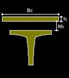
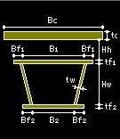
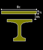
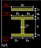
Slab
Slab: Enter the dimensions for slab
Bc: Effective slab width for one girder
tc: Thickness of slab
Hh: Distance from the top of girder to the underside of slab
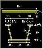
Girder
 : In
the case of Structural steel Box Girder
: In
the case of Structural steel Box GirderHw: Height of web excluding flanges
tw: Thickness of web
B1: Width of top flange (distance between web centers in Box type)
B2: Width of bottom flange (distance between web centers in Box type)
Bf1: Top flange overhang from the center of web in Box type
Bf2: Bottom flange overhang from the center of web in Box type
tf1: Thickness of top flange
tf2: Thickness of bottom flange
Click
 to
define the longitudinal stiffener for Steel Box /
Steel I / Steel Tub section.
to
define the longitudinal stiffener for Steel Box /
Steel I / Steel Tub section.Flat Stiffener Tee Stiffener U-Rib Stiffener
Stiffener: Enter the dimensions of the stiffener as per the image shown above.
.jpg) : Add a new longitudinal stiffener.
: Add a new longitudinal stiffener. : Modify an existing longitudinal stiffener.
.jpg) : Delete the selected longitudinal stiffener
from the list.
: Delete the selected longitudinal stiffener
from the list.Stiffener Position: Chose the stiffener to be positioned on the left or right or both sides of the web of Steel-I girder.
N Left: Number of stiffener on the left web (tub and box girder) or the left of web (I girder).
N Right: Number of stiffener on the right web (tub and box girder) or the right of web (I girder).
N Bottom: Number of stiffener on the bottom flange.
N Top: Number of stiffener on the top flange.
C: Check the box to consider the longitudinal stiffener for the section property calculations. If the box is unchecked then the stiffeners are considered only for design and not for the section property calculations.
 : In
the case of Structural steel I Shape Girder
: In
the case of Structural steel I Shape GirderHw: Height of web excluding flanges
tw: Thickness of web
B1: Width of top flange
B2: Width of bottom flange
tf1: Thickness of top flange
tf2: Thickness of bottom flange
Click
to
define the longitudinal stiffener for Steel Box /
Steel I / Steel Tub section.Flat Stiffener Tee Stiffener U-Rib Stiffener
Stiffener: Enter the dimensions of the stiffener as per the image shown above.
: Add a new longitudinal stiffener. : Modify an existing longitudinal stiffener.: Delete the selected longitudinal stiffener
from the list.Stiffener Position: Chose the stiffener to be positioned on the left or right or both sides of the web of Steel-I girder.
N Left: Number of stiffener on the left web (tub and box girder) or the left of web (I girder).
N Right: Number of stiffener on the right web (tub and box girder) or the right of web (I girder).
N Bottom: Number of stiffener on the bottom flange.
N Top: Number of stiffener on the top flange.
C: Check the box to consider the longitudinal stiffener for the section property calculations. If the box is unchecked then the stiffeners are considered only for design and not for the section property calculations.
 : In
the case of Structural steel I Shape Girder
(including asymmetrical section)
: In
the case of Structural steel I Shape Girder
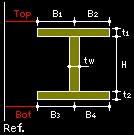
(including asymmetrical section)Symmetric Section Auto Calculation: Check on the option to generate symmetrical section in the element’s local z-axis.
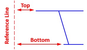
Distance from Reference Line: Specify the value to define asymmetrical section as shown in the figures below. This field will be inactivated when “Symmetric Section Auto Calculation” option is toggled on.
Asymmetrical Slab
Sg: Distance from the left side of the slab to the reference line
Top: Distance from the left side of the top flange to the reference line
Bottom: Distance from the left side of the bottom flange to the reference line
Girder
B1: Top flange left overhang from the center of web
B2: Top flange right overhang from the center of web
B3: Bottom flange left overhang from the center of web
B4: Bottom flange right overhang from the center of web
H: Height of web excluding flanges
t1: Thickness of top flange
t2: Thickness of bottom flange
tw: Thickness of web
Stiffener
Stiffener: define the longitudinal stiffener for Steel Box / Steel I section.
Define Stiffeners: Enter the dimensions of the stiffener as per the image shown below.
Flat Stiffener Tee Stiffener U-Rib Stiffener
Deck & Stiffeners: Enter the position of stiffeners.
Deck Position: Select the position where the stiffener will be positioned among the left/right of the web and top/bottom flange.
Deck Part: Select the flange part where the stiffener will be positioned among flange left/right overhang and flange between web centers
Ref. Point Position: Reference position to determine stiffener position
Left Ref. Point Position Right Ref. Point Position
Stiffener Number: Number of stiffener on the specified deck position and part
C: Check on the option to consider the longitudinal stiffener for the section property calculations. If the box is unchecked, the stiffeners are considered only for design and not for the section property calculation.
Spacing: Distance from the reference point position to enter the stiffener
Stiffener: Select the defined stiffener type from the combo-box. Stiffener can be defined by clicking [Define Stiffener…] button above.
Stiffener Pos.: Stiffener position. Following positions can be selected by Deck Position: For Top Flange, select “Bottom”. For Bottom Flange, select “Top”. For Web, select “Left”, “Right” or “Both”.
Stiffener Names: Enter the stiffener name to be entered in the list.
:
Add a new longitudinal stiffener.: Modify an existing longitudinal stiffener.: Delete the selected longitudinal stiffener
from the list.Note
Limitation: 1. Steel Composite Girder Wizard does not support Steel-I (Type 2) section.
2. Design of steel composite girder defined with Steel-I (Type 2) section is provided only for SNiP/SP design code. As for the Steel-I (Type 1) section, the design to SNiP/SP design code is not supported.
3. Auto-definition of temperature gradient of steel composite girder to the SNiP/SP design code is provided for both Steel-I (Type 1) and Steel-I (Type 2) section.
 : In
the case of Structural steel Tub Shape Girder
: In
the case of Structural steel Tub Shape GirderHw: Height of web excluding flanges
tw: Thickness of web
B1: Clear spacing between the top flanges in Tub type
B2: Width of bottom flange (distance between web centers in Tub type)
Bf1: Top flange width
Bf2: Bottom flange overhang from the center of web in Tub type
tf1: Thickness of top flange
tf2: Thickness of bottom flange
Bf3: Top flange overhang from the center of web in Tub type
tfp: Thickness of fictitious top plate
Note
Steel tub sections have very low inherent torsional resistance. Hence, practically the top flanges of a steel tub are always connected via a bracing to increase this torsional resistance. Ignoring this torsional resistance can lead to erroneous results in pre-composite stage, especially in cases where torsional rigidity plays important role. Example of such cases would be bridges with skew and curvature, wherein the bearing reactions would be greatly altered. General practice in such cases is to idealize this tub section as a box section, wherein the thickness of the top flange is calculated manually depending on the type and spacing of the bracings.
Click
to
define the longitudinal stiffener for Steel Box /
Steel I / Steel Tub section.Flat Stiffener Tee Stiffener U-Rib Stiffener
Stiffener: Enter the dimensions of the stiffener as per the image shown above.
: Add a new longitudinal stiffener. : Modify an existing longitudinal stiffener.: Delete the selected longitudinal stiffener
from the list.Stiffener Position: Chose the stiffener to be positioned on the left or right or both sides of the web of Steel-I girder.
N Left: Number of stiffener on the left web (tub and box girder) or the left of web (I girder).
N Right: Number of stiffener on the right web (tub and box girder) or the right of web (I girder).
N Bottom: Number of stiffener on the bottom flange.
N Top: Number of stiffener on the top flange.
C: Check the box to consider the longitudinal stiffener for the section property calculations. If the box is unchecked then the stiffeners are considered only for design and not for the section property calculations.
 : In the case of Structural steel
Tub Shape Girder (including asymmetrical section)
: In the case of Structural steel
Tub Shape Girder (including asymmetrical section)Symmetric Section Auto Calculation: Check on the option to generate symmetrical section in the element’s local z-axis.
Distance from Reference Line: Specify the value to define asymmetrical section as shown in the figures below. This field will be inactivated when “Symmetric Section Auto Calculation” option is toggled on.
Asymmetrical Slab
Sg: Distance from the left side of the slab to the reference line
Top: Distance from the left side of the top flange to the reference line
Bottom: Distance from the left side of the bottom flange to the reference line
Girder
B1: Top left flange width
B2: Clear spacing between the top flanges in Tub type
B3: Top right flange width
B4: Bottom flange left overhang from the center of web in Tub type
B5: Width of bottom flange (distance between web centers in Tub type)
B6: Bottom flange right overhang from the center of web in Tub type
H: Height of web excluding flanges
t1: Thickness of top flange
t2: Thickness of bottom flange
tw1: Thickness of left web
tw2: Thickness of right web
bf1: Top left flange overhang from the center of web in Tub type
bf2: Top right flange overhang from the center of web in Tub type
tfp: Thickness of fictitious top plate.
Note
Steel tub sections have very low inherent torsional resistance. Hence, practically the top flanges of a steel tub are always connected via a bracing to increase this torsional resistance. Ignoring this torsional resistance can lead to erroneous results in pre-composite stage, especially in cases where torsional rigidity plays important role. Example of such cases would be bridges with skew and curvature, wherein the bearing reactions would be greatly altered. General practice in such cases is to idealize this tub section as a box section, wherein the thickness of the top flange is calculated manually depending on the type and spacing of the bracings.Stiffener
Stiffener: define the longitudinal stiffener for Steel Box / Steel Tub section.
Define Stiffeners: Enter the dimensions of the stiffener as per the image shown below.
Flat Stiffener Tee Stiffener U-Rib Stiffener
Deck & Stiffeners: Enter the position of stiffeners.
Deck Position: Select the position where the stiffener will be positioned among the left/right of the web and top/bottom flange.
Deck Part: Select the flange part where the stiffener will be positioned among flange left/right overhang and flange between web centers
Ref. Point Position: Reference position to determine stiffener position
Top Ref. Point Position Bottom Ref. Point Position
Left Ref. Point Position Right Ref. Point Position
Stiffener Number: Number of stiffener on the specified deck position and part
C: Check on the option to consider the longitudinal stiffener for the section property calculations. If the box is unchecked, the stiffeners are considered only for design and not for the section property calculation.
Spacing: Distance from the reference point position to enter the stiffener
Stiffener: Select the defined stiffener type from the combo-box. Stiffener can be defined by clicking [Define Stiffener…] button above.
Stiffener Pos.: Stiffener position. Following positions can be selected by Deck Position: For Top Flange, select “Bottom”. For Bottom Flange, select “Top”. For Web, select “Left”, “Right” or “Both”.
Stiffener Names: Enter the stiffener name to be entered in the list.
:
Add a new longitudinal stiffener.: Modify an existing longitudinal stiffener.: Delete the selected longitudinal stiffener
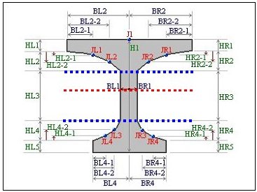
from the list. : In
the case of Composite I Shape
: In
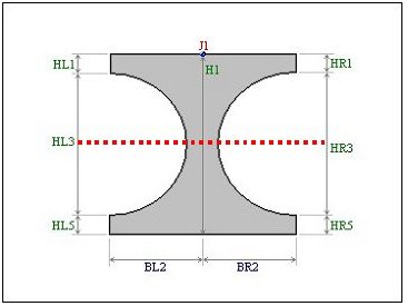
the case of Composite I ShapeJoint on/off: Check on the Joints in the guide diagram to activate the entry fields to additionally define the variant dimensions of the section.
J1, JL1, JL2, JL3, JL4, JR1, JR2, JR3, JR4
Size-I
 :
Import a section defined by PSC Section.
:
Import a section defined by PSC Section.HL1, HL2, HL3,..: Enter the section dimensions referring to the guide diagram.
PSC Viewer: PSC Viewer illustrates the section dimension guide diagram to true scale.
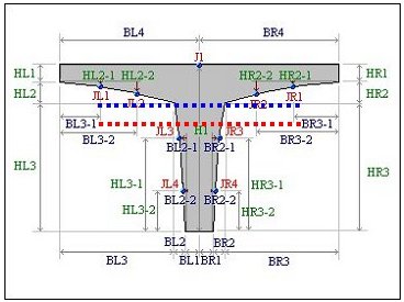
 : In
the case of Composite T Shape
: In
the case of Composite T ShapeJoint on/off: Check on the Joints in the guide diagram to activate the entry fields to additionally define the variant dimensions of the section.
J1, JL1, JL2, JL3, JL4, JR1, JR2, JR3, JR4
Size-I
:
Import a section defined by PSC Section.HL1, HL2, HL3,..: Enter the section dimensions referring to the guide diagram.
PSC Viewer: PSC Viewer illustrates the section dimension guide diagram to true scale.
 : In
the case of Composite PSC Shape
: In
the case of Composite PSC ShapePSC Vaule Type: Click
to import a PSC section from the PSC
Section tab. : In
the case of Composite General Shape
: In
the case of Composite General ShapeWeb thickness for shear(total): Web thickness value used for shear resistance design calculation in composite general section.
 :
In the case of User-defined
Section Shape
:
In the case of User-defined
Section ShapeBefore(After) Composite
If "User" is selected in Section Type, select Before & After Composite sections.Section
Select the section data to be applied s Before/After Composite sections from the section data already defined under other tabs such as DB/User, Value, ect. Material
Click
to
select the material properties for steel and concrete
stored in the DB for a country. The following items are
automatically entered.One material data can be assigned to an element. Composite section consists of two parts, i.e. beam and slab which have two different materials. Thus, assign composite section the material data corresponding to beam and then define material data for the slab from the composite section in terms of ratio of material properties of beam to slab.
Es/Ec: Modulus Ratio, steel to concrete
Ds/Dc: Density ratio, steel to concrete
Note
For the calculation of section properties of Composite Section, concrete is converted into steel. The self-weight is computed as follows:The Weight of Composite Section = Steel Weight + Concrete Weight
If Ds/Dc = 0, concrete weight is ignored and only steel weight is considered.
Ps: Poisson's ratio of steel
Pc: Poisson's ratio of concrete
Ts/Tc (or Tgd/Tsb): Ratio of thermal expansion coefficient of steel and concrete (or Ratio of thermal expansion coefficient of girder and slab)
Note. These ratios will be used when the composite section is used without construction stages where the material data of Composite Section for C.S. will be used with priority.
Multiple Modulus of Elasticity
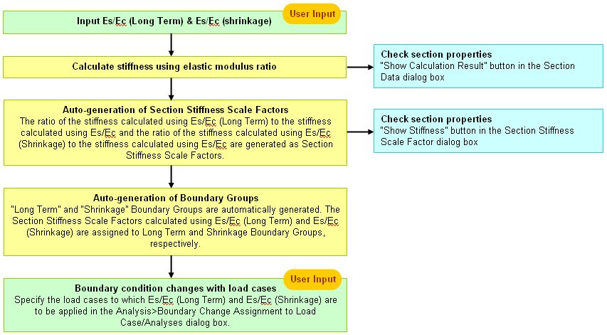
Recalculate the modulus of elasticity of slab concrete to calculate the stresses due to creep and shrinkage. Multiple elastic modulus ratios need to be inputted into an identical section for different load cases. Application of this to analyses and stress checks is specified in EN1994-2 (Eurocode4: Design of composite steel and concrete structures, Part 2) 5.4.2.2.
By checking on this option and entering Es/Ec(Long Term) and Es/Ec(shrinkage), the section properties for post-composite section with those modulus ratios taken into account are calculated.
-
In this dialog box, enter the section property data for steel girder with longitudinal stiffeners. Stiffeners can be defined in Steel Girder I and Steel Girder Box Girder Section.
Section Type: Assign a section type.
Steel Girder Box Steel Girder I
Size
Symmetric Section Auto Calculation: Check on the option to generate symmetrical section in the element’s local z-axis.
Distance from Reference Line: Specify the value to define unsymmetrical section as shown in the figures below. This field will be inactivated when “Symmetric Section Auto Calculation” option is toggled on.
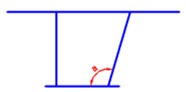
One Inclined Web Unsymmetrical Flanges Inclined Web
Top: Distance from the left side of the top flange to the reference line
Bottom: Distance from the left side of the bottom flange to the reference line
B1: Top flange left overhang from the center of web
B2: Width of top flange (distance between web centers in Box type)
B3: Top flange right overhang from the center of web
B4: Bottom flange left overhang from the center of web
B5: Width of bottom flange (distance between web centers in Box type)
B6: Bottom flange right overhang from the center of web
H: Height of web excluding flanges
t1: Thickness of top flange
t2: Thickness of bottom flange In this dialog box, the sectional data pertaining to the "Analysis considering the section variation before and after composite actions in Composite Bridges" are specified.
tw1: Thickness of left web
tw2: Thickness of right web
B1: Top flange left overhang from the center of web
B2: Top flange right overhang from the center of web
B3: Bottom flange left overhang from the center of web
B4: Bottom flange right overhang from the center of web
H: Height of web excluding flanges
t1: Thickness of top flange
t2: Thickness of bottom flange
Stiffener: define the longitudinal stiffener for Steel Box / Steel I section.
Define Stiffeners: Enter the dimensions of the stiffener as per the image shown below.

Flat Stiffener Tee Stiffener U-Rib Stiffener
Deck & Stiffeners: Enter the position of stiffeners. In this dialog box, the sectional data pertaining to the "Analysis considering the section variation before and after composite actions in Composite Bridges" are specified.
Deck Position: Select the position where the stiffener will be positioned among the left/right of the web and top/bottom flange.
Deck Part: Select the flange part where the stiffener will be positioned among flange left/right overhang and flange between web centers
Ref. Point Position: Reference position to determine stiffener position
Left Ref. Point Position Right Ref. Point Position
Stiffener Number: Number of stiffener on the specified deck position and part
C: Check on the option to consider the longitudinal stiffener for the section property calculations. If the box is unchecked, the stiffeners are considered only for design and not for the section property calculation.
Spacing: Distance from the reference point position to enter the stiffener
Stiffener: Select the defined stiffener type from the combo-box. Stiffener can be defined by clicking [Define Stiffener…] button above.
Stiffener Pos.: Stiffener position. Following positions can be selected by Deck Position: For Top Flange, select “Bottom”. For Bottom Flange, select “Top”. For Web, select “Left”, “Right” or “Both”.
Stiffener Names: Enter the stiffener name to be entered in the list.
 : Add a new
longitudinal stiffener.
: Add a new
longitudinal stiffener. : Modify
an existing longitudinal stiffener.
: Modify
an existing longitudinal stiffener. : Delete the selected longitudinal
stiffener from the list.
: Delete the selected longitudinal
stiffener from the list.
Answer:
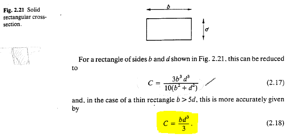
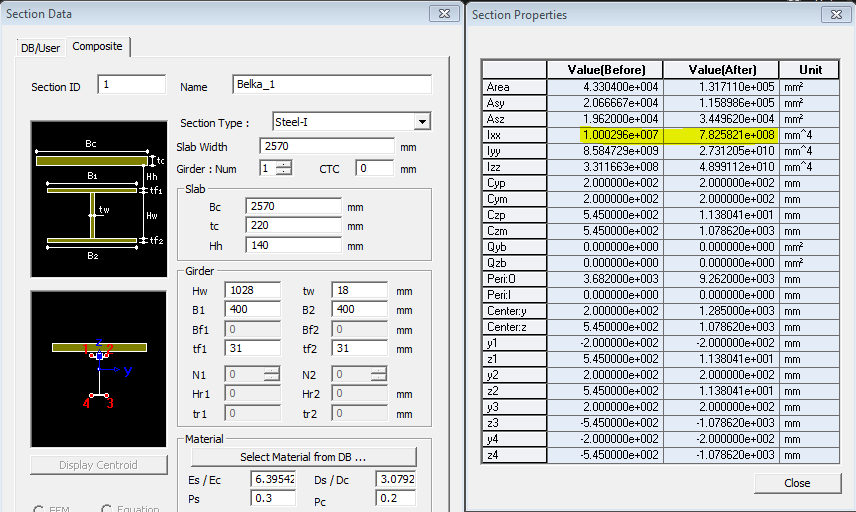
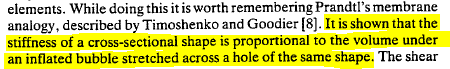
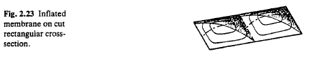
Let me first discuss the results for the section generated using the Composite Steel-I option in Civil. The torsion of such sections is calculated using a method where the section is broken down into rectangles, the torsional constant of each of them is calculated and then the torsion of the combined section is a sum of all the parts. In ‘Bridge Deck Behavior’ by E.C. Hambly we can find detailed information on this approach and how to calculate the torsional constant for a single rectangle:
And
complex sections can be divided in the following manner to
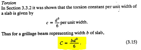
be calculated as rectangles:
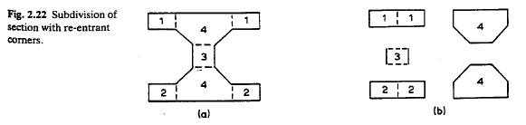
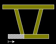
Using this approach we can break your section into 4 parts – bottom flange, web, top flange and slab. Each of those is a thin rectangle and we can apply (2.18) to obtain the torsional constants and then combine them to get the resistance of the composite section (using a modular ratio to convert the contribution of the concrete). In case of composite girders where the slab is continuous and only part of it is effective for the composite action with the steel girder, one more consideration has to be taken into account. The normal distribution of torsion has the following pattern:
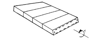
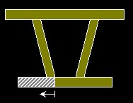
However, for continuous slabs the vertical components at the two ends of the slab are not present for the general case of intermediate girders and the torsional resistance is better approximated by:
Now using (2.18) for the beam parts and (3.15) for the slab we can carry out a manual calculation.
Before
composite: 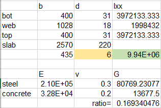
and
after composite: 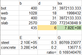
Now if we look at the values provided by the software you will see these match very well.
Now let’s move on to the SPC section. The first thing that needs to be pointed out is that SPC is a tool for calculation of section properties for arbitrary sections, however, as such it has to work for the general case. As I said in my previous email the way SPC calculates section properties is by performing finite element analysis applying unit loads. But when we analyse a composite beam which has a part of a continuous slab acting as flange, the software cannot take into account the reduced torsional resistance of the slab (formula 3.15) as it analyses the beam as a separate unit. So to check the results manually, we have to use (2.18) for the slab as well:
Manual
calculation after composite: 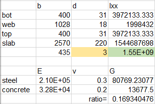
SPC: 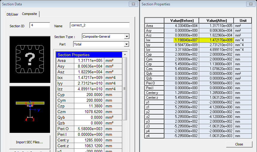
Again, we observe a good match between the values for Ixx after composite. The only significant discrepancy is between the ‘before composite’ values. The Composite Steel – I section gives 1.00E7, while SPC gives 1.2E7. This difference is purely due to the accuracy of the approach using the formulae. After all, this is an approximate method and some inaccuracy is normal. For example, some torsional resistance is lost depending on the division of the section into rectangles as we lose resistance along the dividing lines. Hambly provides a good illustration of this:
You can easily see how splitting the section in this case reduces the value of the resistance obtained.
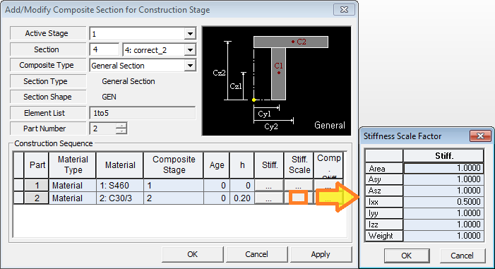
Now that it is clear where the difference in the values is coming from, it is up to engineers to choose what approach they want to use to. As a solution for most accurate calculation I can suggest to use the SPC feature to generate the section with the exact properties and then apply a factor of 0.5 for Ixx for the slab in the Composite Section for Construction Stage definition.
However, as I-beams have generally poor torsional performance, we can simply use the Composite Steel-I section and neglect the inaccuracy of the torsion of the I section as its contribution to the composite properties is negligible (two orders of magnitude lower than the one of the slab). However, if the structure is such that the effects of torsion before composite are important it may be reasonable to go for the more accurate solution with SPC which I suggested above.
I hope this clarifies the topic and you will find this information useful. If there is anything else we could help you with, please let us know.
Kind regards,
MIDAS Support
Answer:
The difference is coming from the way torsional stiffness is calculated using approximating methods (that is, the equation option). In midas Civil the section properties are calculated using approximating simplified methods, while SPC can run an FEM analysis of the section to obtain the section properties. Before continuing with this question please read the answer to Q1.
Now that it is clear how the two methods work, it is easy to see why the equation option provides much lower results.
In this case, as SPC does not support curved lines, the circular parts of the section are represented by a number of straight lines. When we calculate the torsional constant using ‘equation’ the software simply applies the formula for each rectangle (line with thickness) and then sums those up. Obviously, this is incorrect as it completely ignores the connectivity of the lines and the global enclosed shape which the section has and the torsional stiffness which we get is very low. For this reason we have provided an extra function to define the correct stress flow path in such enclosed polygons so that the section properties are calculated correctly. This is done using closed loops (Model > Curve > Closed Loop > Register in SPC). Select the lines on the outer perimeter of the steel section and click apply:
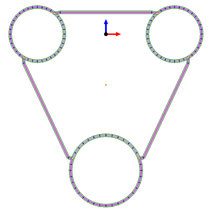
Once this is defined, the torsional constant will be correctly calculated using the equation method as well:
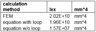
Answer:
There could be two scenarios:
1)
Section Properties cannot be calculated for the defined tapered
section: If this is the case then there could be two possible
reasons as mentioned below.
a) The two pre-defined sections had different number of nodes
in the Section Property Calculator. If the number of nodes/divisions
are different in between the two sections then the software
can't generate a tapered section between them.
b) When the sections are defined in Section Property Calculator,
the software assigns a number to the user defined nodes in
accordance with the sequence of generation. If the sequence
of generation in between the two sections defined in SPC is
different, the software may fail to generate a tapered section
between them because while generating the tapered section,
midas Civil joins the node "x" of one section to
the node "x" to another. Here, "x" is
the node number defined in SPC. In this case, redefining the
section in SPC with same sequence for both the sections is
the solution.
2) Section properties can be calculated but section cannot be defined: This could occur when one of the two predefined sections has zero value for some section property and the other section has non-zero value for the same section property. To define the tapered section successfully, either the section property should be zero for both the sections or non-zero.
For the calculation of torsional constant of Composite Section, Hambly method is used as it is mentioned in the Q1. However, there are slight differences for the calculation of torsional constant of girder section for Composite-PSC section and Composite-Steel sections.
Steel-Box : Ixx = Ixx_girder (Bredt Formula)+ Ixx_slab
Steel-Tub : Ixx = Ixx_girder (Bredt Formula)+ Ixx_slab
Steel-I : Ixx = Ixx_girder (General Formula)+ Ixx_slab
Composite-I, T, PSC, General : Ixx = Ixx_girder(Finite Element Method) + Ixx_slab
Bredt formula represents torsional constant calculation method for thin wall closed section. General Formula represents torsional constant calculation method by breaking up into thin rectangles as described in Q1. FEM is the same method which is used for the calculation of torsional constant of SPC section.
These can cause inevitable differences in terms of torsional constant value in certain cases such as Tub section for the Composite-Steel and Composite-PSC.
For the calculation of torsional constant before composite action, the program assumes that tub section is closed before slab concrete is hardened. During erection in practice, lateral bracings are attached to top flanges in tub girder as shown below.
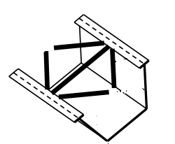
Top flange lateral bracing creates a quasi-closed section, which increases the torsional stiffness of tub girder sections during erection, handling, and deck casting. The top flange lateral bracing forms a quasi-closed section resisting shear flow from the non composite loading. This reflects the practice in the US. If you need to apply any different values of torsional constant, you need to use Section Stiffness Scale Factor. Figure below shows the one of the example comparing tub section Ixx and SPC calculation by modeling it as closed box. When we consider it as closed box, torsional stiffness is almost same.
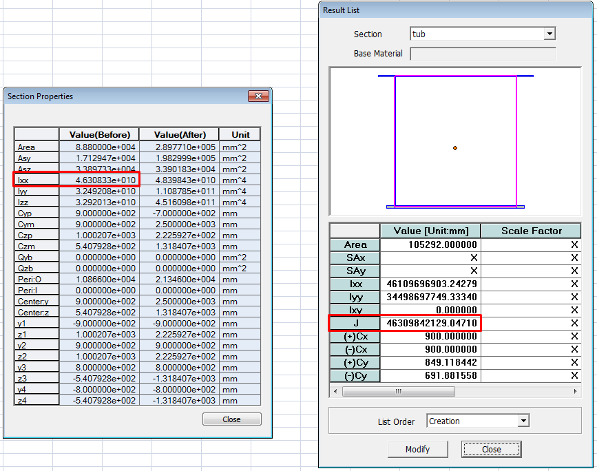
After composite action, the value Ixx is calculated based on the shear modulus ratio (Gs/Gc). When Es/Ec is entered from DB, Poisson's Ratios from DB are used for the calculation of Gs and Gc. When Es/Ec is inputted by the user, Poisson's Ratio is set to 0.
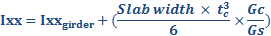
In this case, Ixx_girder is calculated by assuming it as closed section. The torsional constant for closed section used in midas Civil can be found in the following online help.
http://manual.midasuser.com/en_common/civil/845/Start/04_Model/05_Properties/Section.htm
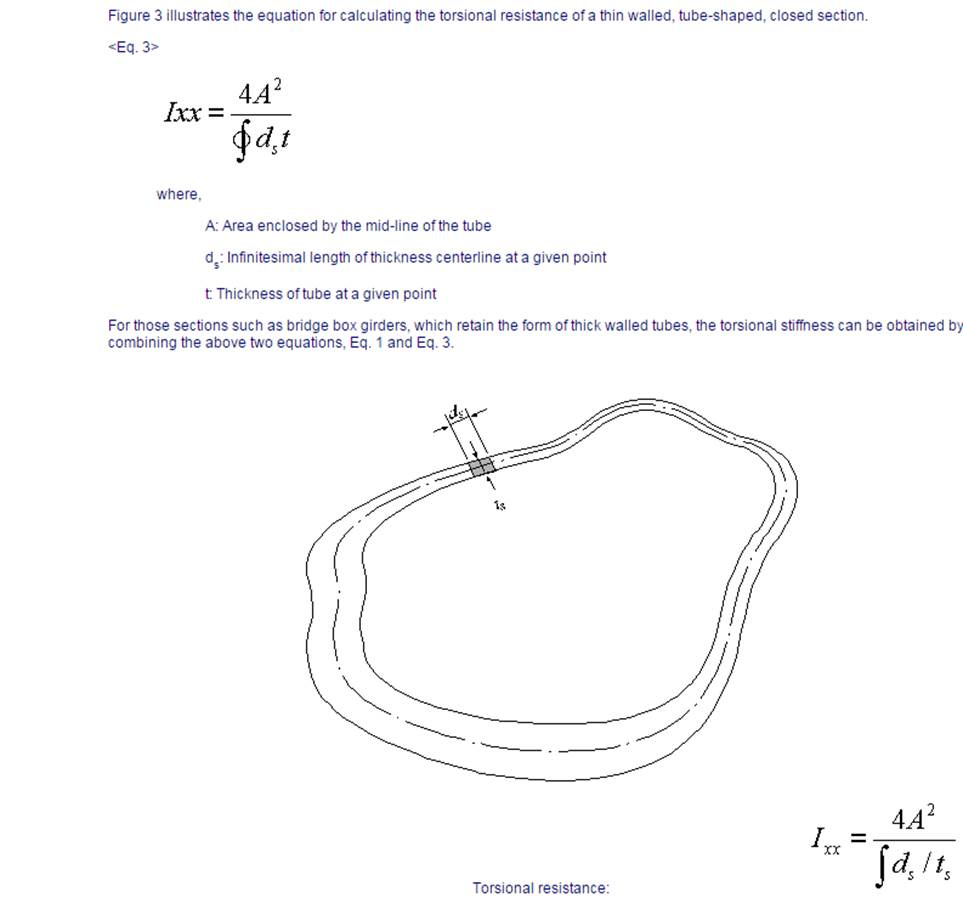
In case
of Composite-PSC, this can be problematic if the girder section
is tub section. Current method of calculation of Ixx of composite
section in Civil cannot recognize whether the section is closed
or not. Therefore there can be discrepancy when the girder
is tub section which makes the whole section as closed section
after the composite action. This limitation can be solved
by modifying Stiffness Scale Factor of torsional constant
manually by the user. This method is also described in Q1,
please refer to the Q1 for the details.