Section for Resultant Forces
This function will enable the users to draw resultant force diagram along the member and generate a table, for the resultant forces (Fx, Fy, Fz, Mx, My, Mz) at several section-cut planes defined along the member. The section-cut plane defined using Section for Resultant Forces option can consist of plate/plane stress elements and/or beam/truss elements.
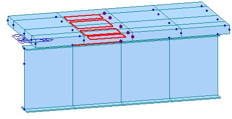
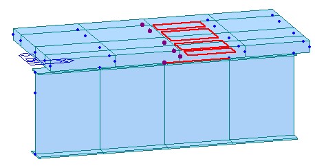
This function is extremely useful for curved or skewed girder bridges which require modelling plate elements for deck. Resultant force diagram using plate and beam forces can be displayed for the defined virtual beams. Applicable analysis type is as follows: Static Analysis, Settlement Analysis, Moving Load Analysis (AASHTO STANDARD/LRFD, Eurocode, BS CODE 5400 & 3701, CANADA, PENNDOT, AUSTRALIA, and TAIWAN), Response Spectrum Analysis and Construction Stage Analysis.
From the Main Menu select Properties > Section > Section for Resultant Forces.
![]() Section for Resultant Forces can be defined using any of the three modes described in detail below:
Section for Resultant Forces can be defined using any of the three modes described in detail below:
Mode: Select the procedure to define the section-cut planes for resultant forces.
If Structure Group is selected


If Elements Select is selected

Note1
Virtual section’s local axis can be displayed from property Tab available under View > Display > Property tab > Virtual Section Local Axis.
Note2
If any change in elements' nodes assigned to virtual section is needed, the user can manually select or deselect the elements or nodes in the model view and click Modify. This will modify the centroid coordinates as per the new virtual section defined. Modify can be used to select or deselect the elements/nodes which is adjacent from the previous virtual section so that the program can automatically detect the new cutting plane.
Note3
The local axis of virtual beam is always oriented along ‘I’ end to ‘J’ end of the virtual sections enclosing the virtual beam. The orientation of local axis of virtual beam must be identical to the local x-axis of virtual section which can be modified using Direction Vector.
Note4
Specifically for curved bridges, users are recommended to use Polygon select mode due to following limitations.
1) Structure group mode may fail to generate the virtual sections when sections lie in a different plane longitudinally due to varying direction vector requirement.
2) Element select option may fail to generate a desired virtual section in case when the selected elements are not in a plane.
Note5
In one virtual section position excepting for the girder start and end, two virtual sections will be automatically generated for i-end and j-end.
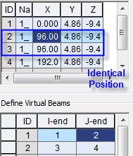
Section ID 2 for j-end of virtual beam ID 1 Section ID 3 for i-end of virtual beam ID 2