Integral Bridge Spring Supports
An integral bridge is one in which the bridge deck and its supporting abutments and piers are integrated without expansion joints to absorb the deformation of the bridge deck using the flexibility of the abutments and piers.
The prime concern in integral bridges is the effects of temperature variations on the deformation of bridge deck. Expansion and contraction of the bridge deck affects the backfill soil adjacent to the abutments. Backfill compaction due to a deck expansion and soil slide due to a deck contraction is repeated. Due to the repeated backfill compaction and soil slide, the modulus of subgrade reaction and the pressure distribution of backfill vary with depth.
A Cycle is the period from a deck expansion to a deck contraction. If cycles are repeated infinitely, the modulus of subgrade reaction of backfill becomes constant. Using the formulation proposed by B.M. Lehane, soil springs can be assigned.
To account for this characteristic of the soil, lateral springs are modeled as compression-only springs and vertical springs are modeled as linear elastic springs.
From the Main Menu select Boundary > Spring Supports > Integral Bridge.
![]() Abutment
Spring
Abutment
Spring
Springs
are automatically assigned to backfill and foundations. Backfill
soil is defined as compression-only springs (![]() )
and foundations are defined as linear elastic springs (
)
and foundations are defined as linear elastic springs (![]() ).
Entered data can be checked from Point
Spring Supports Table.
).
Entered data can be checked from Point
Spring Supports Table.
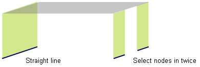
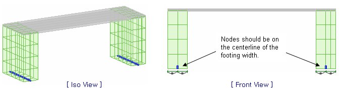
Direction: Select the direction in which Elastic Links are to be assigned. Element List: Select the abutment elements to which backfill soil springs are to be assigned.
Abutment Height (H) Abutment Width (B) Deck Length (L): Deck length along the longitudinal direction
Void Ratio (e): Ratio of void to backfill soil Specific Gravity (Gs): The density of backfill soil. In general, 2.65. Cycle factor (fcyc): This factor is assessed at about 2 based on the test conducted by [Cosgrove et al (2001)]. And this incorporates the reduction in void ratio brought about by cycling. Deck is expanded and contracted due to temperature variations. Integrated abutment is also deformed together. This is a factor used in the empirical formula which accounts for the state after infinite cycles.
Differential Deck Temp.: Temperature increment of deck α: Thermal expansion coefficient of deck
Found. Width (W): The width of foundation Found. Bearing Pressure (p'): Foundation bearing pressure Rot. Spring Dir.: Rotational direction of the foundation. If the longitudinal direction of the foundation is y, select Ry. |
![]() Computation of Stiffness
of Compression-only Springs for Abutment Backfill
Computation of Stiffness
of Compression-only Springs for Abutment Backfill
Stiffness per Unit Area
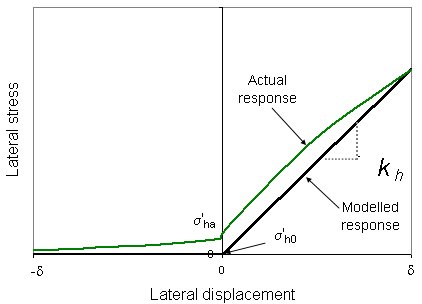
According to Broms (1971), the lateral stress-displacement relationship
for abutment backfill of Integral Bridge is determined as shown
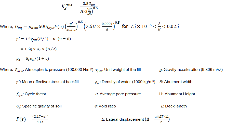
in the figure above. The stiffness per unit area is calculated
as follows:
Spring
Stiffness
The final spring stiffness is determined by multiplying the stiffness
per unit area by the area.
![]()
![]() Computation of Stiffness
of Linear Elastic Springs for Foundation
Computation of Stiffness
of Linear Elastic Springs for Foundation
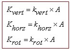
Stiffness per Unit Area
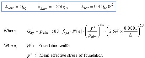
Spring
Stiffness
The final spring stiffness is determined by multiplying the stiffness
per unit area by the area.
![]() Pile Spring
Pile Spring
Assign
the springs for the soils adjacent to piles. Lateral springs for
the soils adjacent to piles are modeled as symmetric nonlinear
elastic springs (![]() )
and vertical springs for the soils adjacent to piles are modeled
as linear elastic springs (
)
and vertical springs for the soils adjacent to piles are modeled
as linear elastic springs (![]() ).
).
The stiffness of soil springs is automatically calculated and entered into Point Spring Supports. The entered data can be checked from Point Spring Supports Table.
Select the frame element to which the pile springs have to be assigned. Soil Type: Soil Types are classified into Sand / Soft Clay / Stiff Clay. Depending upon the selected Soil Type, stiffness calculation method will be different. Methods of calculating spring stiffness are explained at the bottom. Ground Level: Z coordinate of ground Pile Diameter (D) Unit Weight of Soil (γ) Earth Pressure Coeff. at rest (K0): Coefficient of earth pressure at rest Coeff. of Subgrade Reaction (Kh): Modulus of subgrade reaction Internal Friction Angle (Φ): Angle of internal friction of soil Initial Soil Modulus (k1): Constant determined according to the relative density. Determines the stiffness of nonlinear elastic lateral springs for the soils adjacent to piles. Refer to Computation of Points k and m shown below.
Note The elements to which the pile springs are assigned should have their local axis aligned in the same direction.
|
![]() The Stiffness of Nonlinear
Elastic (Lateral) Springs for the Soils adjacent to Piles
The Stiffness of Nonlinear
Elastic (Lateral) Springs for the Soils adjacent to Piles
|
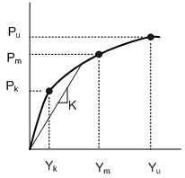
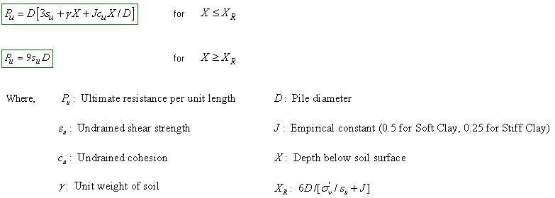
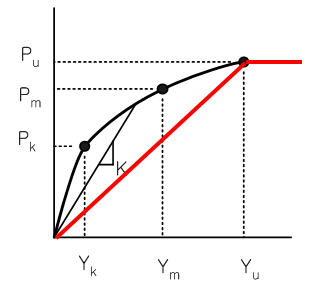
The relationship between the lateral soil resistance and the lateral displacement Y at a specific depth X is represented as shown in the left figure. The values of Pk, Pm, Pu, Yk, Ym and Yu are defined at a specific depth (i.e., where pile springs are). The method of calculating Pu varies with Soil Types. The values of Pk, Pm, Yk, Ym and Yu are calculated using Pu as explained below. The calculation method is divided into two major cases - Sand and Clay. Different J values are used for Soft Clay and Stiff Clay, respectively. |
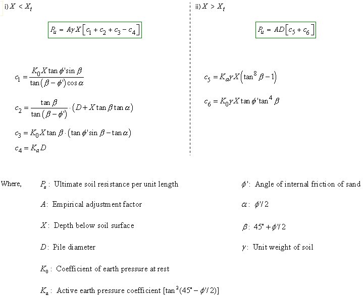
Calculation of Pu in case of Sand Soil
The value of Xt denotes the depth when the following two Pu values
are equal. Make the right terms of two equations equal, rearrange
the equation in terms of X and solve the quadratic equation
Calculation of Pu in case of Clay Soil
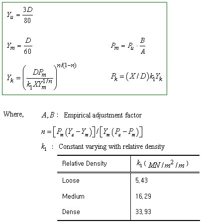
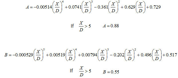
Computation of Points k and m
Note
If Yk is greater than Ym and less than Yu, the p-y curve will be tri-linear as shown below.
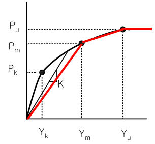
If Yk is greater than Yu, the p-y curve will be bi-linear as shown below.
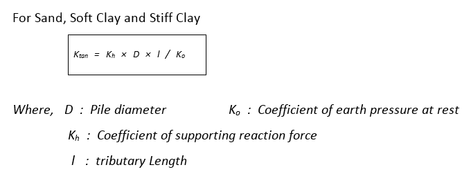
Spring
Stiffness
The final spring stiffness is determined by multiplying the stiffness
per unit area calculated above by the area.
![]()
![]() The Stiffness of Linear
Elastic (Vertical) Springs for the Soils adjacent to Piles
The Stiffness of Linear
Elastic (Vertical) Springs for the Soils adjacent to Piles
The direction of the linear elastic vertical springs for the soils adjacent to piles should be perpendicular to the ground (GCS '-'Z direction). Even though the piles are not perpendicular to the ground, the z-direction (Node Local Axis) of the nodes for Piles should coincide with the GCS Z-direction.