Linear Constraints
Constrain a specific node to subordinate to the movements of certain nodes. Here, the specific subordinate node is referred to as a constraint node, and the nodes to which the specific node is subordinated are referred to as independent nodes. The relationship between the constraint node and the independent nodes is established.
|
|
Constraining translational displacement Eq. (1) |
|
|
Constraining rotational displacement Eq. (2) |
where,
![]() : Translational displacement of constraint node, m in M-direction
: Translational displacement of constraint node, m in M-direction
![]() : Translational displacement of independent node, i in I-direction
: Translational displacement of independent node, i in I-direction
![]() : Rotational displacement of constraint node, m about M-direction
: Rotational displacement of constraint node, m about M-direction
![]() : Rotational displacement of independent node, i about I-direction
: Rotational displacement of independent node, i about I-direction
![]() : Coefficients defining correlation among degrees of freedom
: Coefficients defining correlation among degrees of freedom
Since the constraint Eq. (1) or (2) allows to constrain any node and any DOF, the range of their applications is quite extensive. The constrain equations are applied to the degrees of freedom defined in GCS.
Fig. 1 shows an application example in which a connection is made between a 3-D structure consisted of solid elements and a thin plate consisted of plate elements. Since solid elements do not have stiffness against rotational DOF, they cannot restrain the rotational behavior of the connected plate. If the rotational DOF of the connected part is restrained using Eq. (3), the plate elements would generally behave perpendicularly to the connection.
|
|
Eq. (3) |
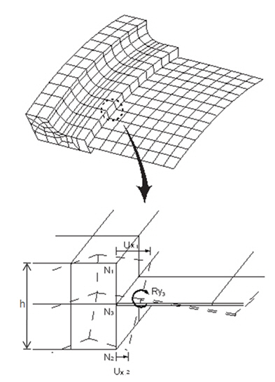
Figure 1 Example of constraint equation application
It must be made clear not to confuse the constraint equations with Rigid Link. Rigid Link is one in which a number of nodes are subordinated to the movement of a single node. Whereas a constraint condition by the constraint equations is one in which a single node is subordinated to the movements of a number of independent nodes.
From the Main Menu select Boundary > Etc. > Linear Constraints.
![]() Boundary Group Name
Boundary Group Name
Select a Boundary Group in which the specified boundary condition is included. Select "Default" if Group assignment is unnecessary. Click ![]() to the right to prompt the "Define Boundary Group" dialog box to add, modify or delete Boundary Groups.
to the right to prompt the "Define Boundary Group" dialog box to add, modify or delete Boundary Groups.
![]() Options
Options
Add/Replace: Assign selected nodes as constraint node or modify linear constraint conditions
Delete: Delete linear constraint conditions of selected nodes
![]() Type
Type
There are two methods by which the constraint equations are assigned. The explicit method is one in which constraint equations are generated by directly entering all the DOF and coefficients of Eq. (1) or (2) above. And the weighted displacement method is one in which the movement of the constraint node is made equal to the average displacement of independent nodes. Both of which are outlined below.
Explicit
- Select a constraint node and DOF (multi-selection is not allowed).
- Select independent nodes and DOF (multi-selection is not allowed), and input coefficients (![]() or
or ![]() )
)
Information on independent nodes can be repeatedly input, and Eq. (1) or (2) above is created through this process.
Weighted displacement
- Select a constraint node.
- Select DOFs (multi-selection is allowed) to be commonly applied for the constraint node and independent nodes.
- Select each independent node and input a weight factor, ![]() .
.
Information on independent nodes can be repeatedly input, and the following constraint equations are created:
![]() or
or ![]()
where, S is the sum of the weight factors (![]() ). This method does not result in coupling of translational displacement and rotational displacement.
). This method does not result in coupling of translational displacement and rotational displacement.
-
When type is Explicit
|
Node : Select a node which is constrained to another nodes. DOF : Assign the degrees-of-freedom of the constraint node.
Node : Select node(s) which will be used to compute displacement of Constraint Node. DOF : Assign the degrees-of-freedom of the independent node. Coeff. : Coefficients defining correlation among degrees of freedom for displacement of Independent Node Note 1 Coefficients are automatically changed by the unit of length when translational DOF(DX, DY or DZ) and rotational DOF(RX, RY or RZ) is constrained to each other. Note 2 In general, assigned DOFs are along the global axis. However, when Node Local Axis is assigned to the constrained nodes, the DOF is based on the local axis.
|
|
|
|
|
-
When type is Weighted Displacement
|
Node : Select a node which is constrained to another nodes. DOF : Assign the degrees-of-freedom of the constraint node.
Node : Select node(s) which will be used to compute displacement of Constraint Node. Weight : Weighting factor defining correlation among degrees of freedom. Note In general, assigned DOFs are along the global axis. However, when Node Local Axis is assigned to the constrained nodes, the DOF is based on the local axis. |
Example How to constrain translational displacements two nodes which are not aligned along the global axis
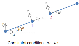
Method 1. Using Node Local Axis
If a Node Local Axis is pre-assigned to node with 30˚ angle from the global, the coefficient can become simply 1.
![]()
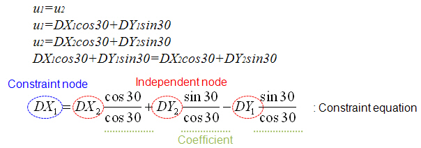
Method 2. Assigning coefficients manually
If node local axis is not assigned, user must compute the coefficients considering position of two nodes. Here, the coefficients equal to 'cos30/cos30' for x2, 'sin30/con30' for y2 and 'sin30/cos30' for y1 respectively according to the following relationship.
Where,
![]() : Translational displacement of constraint node 1 in X-direction
: Translational displacement of constraint node 1 in X-direction
![]() : Translational displacement of independent node 2 in X-direction
: Translational displacement of independent node 2 in X-direction
![]() : Translational displacement of independent node 1 in Y-direction
: Translational displacement of independent node 1 in Y-direction
![]() : Translational displacement of independent node 2 in Y-direction
: Translational displacement of independent node 2 in Y-direction