Define Sub Domain
Sub-Domain is the unit area of mesh elements. When generating a mesh, the entire mesh area is the Domain and the mesh elements that partition the mesh are the Sub-Domains. A Sub-Domain can be defined automatically when a mesh is generated or can be defined directly from the Define Sub-Domain dialog box. Sub-Domains are automatically assigned numerical names when created (1, 2, 3,...).
The automatically assigned name of each Sub-Domain is created like [1], [2], [3].
From the Main Menu select Node/Element > Elements > Define Sub-Domain.
|
Name: The name of the Domain that will be defined with a Sub-Domain. Element Type: The Element Type of the Domain that will be defined with a Sub-Domain.
Name: Name of the Sub-Domain Member Type: Plate Beam (1D), Plate Column (1D) or Shell are provided as member type and Beam/Column is classified according to member type. Plate Beam (1D): Select to consider Slab Design like one-way Beam. Plate Column (1D): Select to consider Abutment/Side Wall Design like Column considering axial force and moment. Shell: Select to consider Shell Design Note Rebar Direction: Define the direction of the reinforcement. Local : Define rebar direction along the Local Coordinate System of the plate element. UCS: : Define rebar direction along the predefined User Coordinate System. If UCS is not specified, the Global Reference Axis : Define rebar direction along the user defined Reference Axis. Two nodes for V1 are selected to define Note
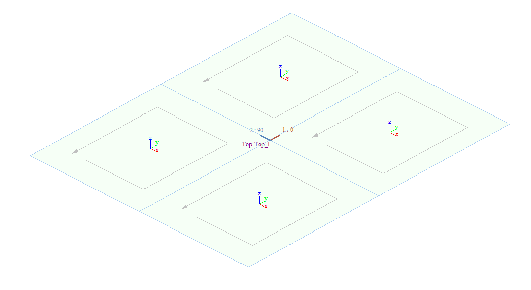
Rebar Dir. (CCW) Dir. 1: Angle from Reference x: The major direction of the reinforcement. Enter the rotational angle with respect to the reference x-axis. Dir. 2: Angle from Dir-1: The minor direction of the reinforcement. Enter the rotational angle formed from the major direction of the reinforcement (Angle 1). V1: Vector defining the reference x-axis V2: Any vector defining x-y plane
The elements that belong to the Sub-Domain. The elements that belong to the Sub-Domain should be adjacent to each other.
Add : After defining the Sub-Domain data, select Add to generate the new Sub-Domain. The new Sub-Domain will be listed below, showing the Name, Type, Angle, and Elements. Modify : Select a specific Sub-Domain from the Sub-Domain list and the data will be displayed in the upper sections of the dialog box. Modify the information of the selected Sub-Domain and click Modify to save the new data. Delete : Select a Sub-Domain from the list and click Delete to delete the selected Sub-Domain. |