Temperature Gradient
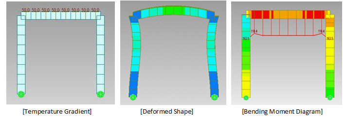
Enter the temperature differences between the tops and bottoms of beam or plate elements for thermal stress analysis. Modify or delete previously entered temperature differences.
The temperature gradient analysis is applicable for elements with bending stiffness such as beam and plate elements. In the case of a beam element, enter the temperature difference and the corresponding distance between the extremities of the element with respect to the local y and z-axes. In the case of a plate element, the temperature gradient can be represented by the temperature difference between the upper and lower faces of the plate and the plate thickness. The gradient temperature produces the following equivalent moments:
-
-
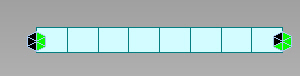
In the case of a beam element
-

-
-
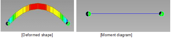
In the case of a plate element
-
Where, ![]() is the linear thermal expansion coefficient, E is the modulus of elasticity, I is the moment of inertia about the relevant axis of the beam element,
is the linear thermal expansion coefficient, E is the modulus of elasticity, I is the moment of inertia about the relevant axis of the beam element, ![]() is the temperature difference between the two extremities (outermost faces) of the element, h is the distance between the two extremities of the beam section, t is the thickness of the plate and
is the temperature difference between the two extremities (outermost faces) of the element, h is the distance between the two extremities of the beam section, t is the thickness of the plate and ![]() is the Poisson's Ratio.
is the Poisson's Ratio.
From the Main Menu select Load > Temp/Prestress > Temp. Gradient.
|
 Types, Gradient
Select the element type for which Temperature Gradient is to be specified. Refer to the figure to enter the required data.
Beam
T2z - T1z: Temperature difference between the two outermost faces in the element local z-direction
Use Section Hz: Use the section dimension information as is.
Hz: Distance between the two faces in the element local z-direction
T2y - T1y: Temperature difference between the two outermost faces in the element local y-direction
Use Section Hy: Use the section dimension information as is.
Hy: Distance between the two faces in the element local y-direction
Plate
T2z - T1z: Temperature difference between the two faces in the element local z-direction
Use Section Hz: Use the section dimension information as is.
Hz: Thickness of the plate element
![]() Revision of Civil 2015 (v1.1)
Revision of Civil 2015 (v1.1)