Traffic Surface Lanes
Enter the traffic surface lanes for moving load analysis.
From the Main Menu select Load > Moving Load > Traffic Surface Lanes.
![]()
To enter new or additional traffic surface lanes
![]()
To modify previously entered traffic surface lanes
Select a Lane Name for which lane information is to be modified.
![]()
To delete previously entered traffic surface lanes
Select a Lane Name for which lane information is to be deleted.
![]()
To copy previously entered traffic surface lanes
Select a Lane Name for which lane information is to be copied.
 Lane Name
Enter the name of a traffic surface lane.
Traffic Lane Properties
Lane Width
Enter the width of a traffic surface lane.
Wheel Spacing
Enter the spacing between the wheels. For influence line analysis, the program automatically applies a load equal to "load ÷ of wheels" to each wheel.
|
|
|
|
Truck Load |
Lane Load |
For influence line analysis, Uniform Lane Load is loaded to each wheel as a uniform line load, which is the load per unit length divided by no. of wheels. For influence surface analysis, Uniform Lane Loads are applied as uniform area loads acting on the traffic lane surface.
For influence line analysis, Concentrated Lane Load divided by no. of wheels is applied to each wheel. Concentrated Lane Load needs to be applied as a uniform line load perpendicular to the traffic line lane, but this is not supported in influence line analysis using beam elements. For influence surface analysis using plate elements, Concentrated Lane Load divided by no. of wheels is applied to each wheel. Applying Concentrated Lane Load as a uniform line load is currently not available.
 Offset Distance to lane center
Enter the distance from the line of traffic lane nodes to the center of the traffic surface lane. Viewing towards the moving direction of the traffic surface lane, a positive eccentricity (+) refers to an offset to the right from the traffic lane nodes and a negative eccentricity (-) refers to an offset to the left from the traffic lane nodes.
Impact Factor
Enter the impact factor for the entered traffic surface lane being defined.
Skew
Enter the skewed angles at the start and end of the bridge referring to the diagram.
Eccentricity of Vertical Load to consider Cant
The eccentricity of loading with respect to the center-line of the track.
The effect of cant, relative vertical distance between the uppermost surface of the two rails at a particular location along the track may be considered by taking the eccentricity of loading with respect to the center-line of the track, which will result in the increase in the wheel load on the inside of the curve and a concomitant decrease in the outside wheel load.
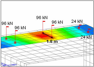
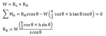
The wheel load reactions, RL and RR are calculated by summing moments about Point O and enforcing equilibrium.
If the slope is 5%,  (s = 2.0m, h = 2.0m)

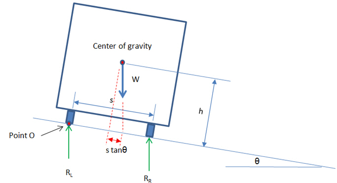
Figure 1. Effects of cant of the wheel load reactions
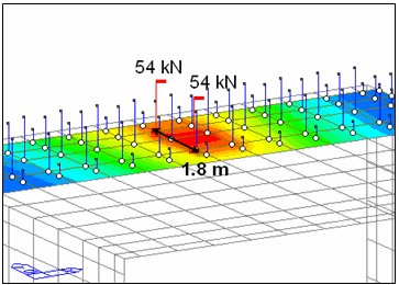
This can be simulated by applying the eccentricity of vertical loads. In the above case, the associated eccentricity can be calculated by summing moments about the center of gravity as follows:
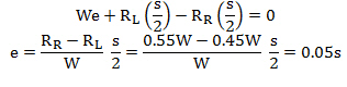
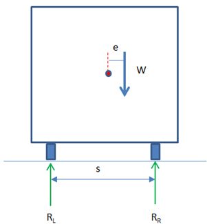
Figure 2. Eccentricity of vertical loads
Moving Direction
Define the direction of the vehicular loading.
Forward: consider only the direction from the start to end.
Backward: consider only the direction from the end to start.
Both: consider both vehicular loading direction.
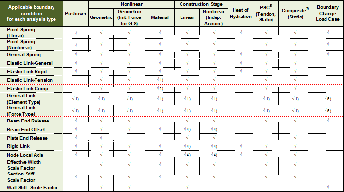
Supported Code : AASHTO standard, AASHTO LRFD, PENNDOT, Canada, Australia, Korea, KSCE-LSD15, India, Taiwan
Unsupported Code : BS, EUROCODE, Russia, China
Selection by
Specify the method of defining a traffic lane node line to define a traffic surface lane.
![]() 2 points
2 points
Use the coordinates of two points to enter a traffic lane node line.
All the nodes connecting these two points constitute a traffic lane node line.
![]() Picking / Number
Picking / Number
Select all the nodes along the traffic lane node line.
Use the mouse or directly enter the node numbers to create a traffic lane node line.
Note
The traffic surface lane is defined by the traffic lane node line, eccentricity and traffic lane width. The traffic surface lane is created by placing the traffic lane center offset by an eccentricity distance from the traffic lane node line. Extending 1/2 of the lane width on both sides of the lane center while looking towards the moving direction defines the traffic surface lane.
Operations
Entry is reflected when Selection by Number is used.
![]() : Add selected nodes to the traffic lane node line.
: Add selected nodes to the traffic lane node line.
![]() : Insert selected nodes to become a part of the previously entered traffic lane node line.
: Insert selected nodes to become a part of the previously entered traffic lane node line.
![]() : Delete selected nodes from the traffic lane node line.
: Delete selected nodes from the traffic lane node line.
![]() Span Start
Span Start
For multi-span bridges, select the starting element of each span to distinguish spans. This is used to calculate the maximum negative moment of a continuous bridge due to DL.
![]() Revision of Civil 2014 (v2.1)
Revision of Civil 2014 (v2.1)