Vehicles
Enter vehicle loads.
From the Main Menu select Load > Moving Load > Vehicles.
![]() To enter
new or additional vehicle loads
To enter
new or additional vehicle loads
Click
![]() when a vehicle load conforms
to designated standards.
when a vehicle load conforms
to designated standards.
 AASHTO Standard Load
Enter the vehicle loads specified in AASHTO standard.
.jpg)
 AASHTO Legal
Load
Enter the vehicle loads specified in AASHTO Legal Loads.
 Caltrans Standard
Load
Enter the vehicle loads specified in Caltrans Specification.
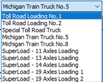
 Turkey
Enter the vehicle loads specified in Turkey specifications.
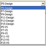
 Others
Enter the vehicle loads specified in PENNDOT and Australian specifications.

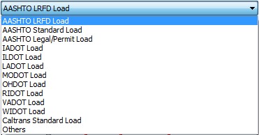
DOT rating vehicle loadings are implemented for load rating.
 AASHTO
LRFD Load
Enter the vehicle loads specified in AASHTO LRFD standard.
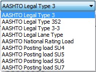
 AASHTO Legal/permit Load
Enter the vehicle loads specified in AASHTO Legal/permit Specification.
 IADOT Load
Enter the vehicle loads specified in IADOT Specification.

 ILDOT Load
Enter the vehicle loads specified in ILDOT Specification.

 INDOT Load
Enter the vehicle loads specified in INDOT Specification.
 LADOT
Load
Enter the vehicle loads specified in LADOT Specification.

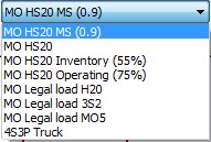
 MODOT Load
Enter the vehicle loads specified in MODOT Specification.
 OHDOT Load
Enter the vehicle loads specified in OHDOT Specification.

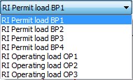
 RIDOT Load
Enter the vehicle loads specified in RIDOT Specification.
 VADOT Load
Enter the vehicle loads specified in VADOT Specification.

 WIDOT Load
Enter the vehicle loads specified in WIDOT Specification.

 Caltrans
Standard Load
Enter the vehicle loads specified in Caltrans Specification.

 Turkey
Enter the vehicle loads specified in Turkey Specification.
 Colombia
Enter the vehicle loads specified in Turkey Specification.
CCP-14 Truck
CCP-14 Tandem
 Others
Enter the vehicle loads specified in UIC and Australian specifications.

PENNDOT
Enter the vehicle loads specified in PENNDOT specification.
 Others
Enter the vehicle loads specified in PENNDOT and Australian specifications.

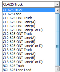
 Canadian
Standard Load
Enter the vehicle loads specified in Canadian Standard.
Dynamic Load Allowance
Auto: Apply Dynamic Load Allowance factor as per Canadian specification
User Input: Apply Dynamic Load Allowance factor using user input value
As specified in the code, it is differently applied for the following condition.
Where only one axle of the CL-W Truck is used
Where any two axle or axles 1,2 and 3 are used
Where three axles except for axles 1,2 and 3 or more than three axles are used
Note.
The applied dynamic load allowance factor can be checked by lanes in the moving load tracer by clicking [Detail Results] button.
 BS5400
Standard Load
Vehicular Load Name: Enter the name of the vehicular load.
Vehicular Load Type: Enter the type of the vehicular load.
Enter the vehicle loads specified in BS5400 Standard.
![]()
No. of Units: Minimum number of loads for HB Type vehicle load. (Usually this is considered to be 30)
![]() BD37/01 Standard Load
BD37/01 Standard Load
Enter the vehicle loads specified in BD37/01 Standard.

HA Loading
BD 37/01
Enter HA vehicle loads specified in BD 37/01 Standard. HA Lane Factors are automatically calculated as per BD 37/01.
BD 21/01
Enter HA vehicle loads specified in BD 21/01 Standard. HA Lane Factors are applied as follows as per BD 21/01.
Lane 1: 1.0, Lane 2: 1.0, Lane 3: 0.5, Lane 4 and subsequent: 0.4
Additional Data
Adjustment Factor: The HA UDL and KEL are adjusted in order to eliminate the lateral bunching factor by dividing by dividing by the Adjustment Factor (AF). Clause 5.23 of BD 21/01
Reduction Factor: The Reduction Factor (K) is the ratio of Assessment Live Loading effects/Type HA loading effects. Both the UDL and the KEL parts of the type HA loading are reduced by an identical Reduction Factor for each of the Assessment Live Loadings. Clause 5.20 of BD 21/01
User-defined
HA Lane Factors are considered with the value defined by the user.
HB Loading
Enter HB vehicle loads specified in BD37/01 Standard.
HA & HB Loading
BD 37/01
Enter HA and HB loading combined in one lane specified in BD37/01 Standard. HA UDL in a lane shall be loaded to the total length displaced by HB loading with the front and rear clear spaces (dd). HA Lane Factors are automatically calculated as per BD 37/01.
BD 21/01
Enter HA vehicle loads specified in BD 21/01 Standard. HA Lane Factors are applied as follows as per BD 21/01.
Lane 1: 1.0, Lane 2: 1.0, Lane 3: 0.5, Lane 4 and subsequent: 0.4
Additional Data
Adjustment Factor: The HA UDL and KEL are adjusted in order to eliminate the lateral bunching factor by dividing by dividing by the Adjustment Factor (AF). Clause 5.23 of BD 21/01
Reduction Factor: The Reduction Factor (K) is the ratio of Assessment Live Loading effects/Type HA loading effects. Both the UDL and the KEL parts of the type HA loading are reduced by an identical Reduction Factor for each of the Assessment Live Loadings. Clause 5.20 of BD 21/01
User-defined
HA Lane Factors are considered with the value defined by the user.
HA & HB (Auto) Loading
BD 37/01
Enter HA and HB loading combined for the entire lanes so that the program can automatically organize live load combination specified in BD37/01 Standard as shown in the figures below.
HA loading shall be applied to the notional lanes of the carriageway. HA UDL and KEL shall be multiplied by the lane factor. HA Lane Factors are automatically calculated as per BD 37/01. HB loading shall occupy any transverse position on the carriage way, either wholly within one notional lane or straddling two notional lanes.
BD 21/01
Enter HA vehicle loads specified in BD 21/01 Standard. HA Lane Factors are applied as follows as per BD 21/01.
Lane 1: 1.0, Lane 2: 1.0, Lane 3: 0.5, Lane 4 and subsequent: 0.4
Additional Data
Adjustment Factor: The HA UDL and KEL are adjusted in order to eliminate the lateral bunching factor by dividing by dividing by the Adjustment Factor (AF). Clause 5.23 of BD 21/01
Reduction Factor: The Reduction Factor (K) is the ratio of Assessment Live Loading effects/Type HA loading effects. Both the UDL and the KEL parts of the type HA loading are reduced by an identical Reduction Factor for each of the Assessment Live Loadings. Clause 5.20 of BD 21/01
User-defined
HA Lane Factors are considered with the value defined by the user.
Pedestrian
Enter foot/cycle track bridge live loads specified in BD37/01 Standard.
![]() CS 454 Assessment
CS 454 Assessment
Enter the vehicle loads specified in CS 454 standard.
ALL Model 1
Vehicular Load Name: Enter the name of vehicle.
Sub Type: Select one of the vehicle load models for normal and restricted loading levels.
Loading Case: Select Single or Convoy.
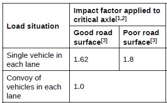
The ALL model 1 shall consist of vehicle loads, applied in the following situations, considered separately.
1) single vehicle in each lane
2) a convoy of vehicles in each lane
Load Surface: Select Good or Poor to determine impact factor.
Traffic Flow Category: Select High or Medium or Low to determine traffic flow factor.
High: 1.0, Medium: 0.95, Low: 0.9
Note:
1. Lane Factors
Lane Factors for ALL model 1 will be automatically applied as per CS 454 specification.
Lane 1: 1.0, Lane 2: 1.0, Lane 3: 0.5, Lane 4 and subsequent: 0.4
The lane factors are interchangeable between lanes.
2. Remaining Area
Where the assessment live loading exceeds 7.5 tonnes, a UDL of 5 KN/m2 shall be applied over the remaining area of carriageway, except where this provides a relieving effect. The user needs to create a lane to represent remaining area and define it as remaining area in the Moving Load Case. Then, UDL of 5 kN/m2 will be applied to the lane.
ALL Model 2 (UDL+KEL)
Lane Factor
CS 454
Lane Factors are automatically calculated as per CS 454.
User-defined
Lane Factors are considered with the values defined by the user.
Category for K Factor
CS 454
The K factors accounts for surface category and traffic flow category given in Figures 5.19a to 5.19f and Table 5.19c. Clause 5.19 of CS 454.
![]() BD86/11 Standard Load
BD86/11 Standard Load
Enter the special vehicle loads specified in BD86/11 Standard.
SV 80
The SV 80 load model is intended to model the effects of STGO Category 2 vehicles with a maximum gross vehicle weight of 80 tonnes and a maximum basic axle load of 12.5 tonnes.
SV 100
The SV 100 load model is intended to model the effects of STGO Category 3 vehicles with a maximum gross vehicle weight of 100 tonnes and a maximum basic axle load of 16.5 tonnes.
SV 150
The SV 150 load model is intended to model the effects of STGO Category 3 vehicles with a maximum gross vehicle weight of 150 tonnes and a maximum basic axle load of 16.5 tonnes.
SV 196
The SV 196 load model represents the effects of a single locomotive pulling a STGO Category 3 vehicles with a maximum gross vehicle weight of 100 tonnes and a maximum basic axle load of 16.5 tonnes. (UK National Annex to Eurocode 1)
SV-Train
The SV-Train load model is intended to model the effects of a single locomotive pulling a STGO Category 3 vehicles with a maximum gross vehicle weight of 100 tonnes and a maximum basic axle load of 16.5 tonnes.
SOV 250
Maximum total weight of SO trailer units up to 250 tonnes.
SOV 350
Maximum total weight of SO trailer units up to 350 tonnes.
SOV 450
Maximum total weight of SO trailer units up to 450 tonnes.
SOV 600
Maximum total weight of SO trailer units up to 600 tonnes.
Dynamic Amplification Factor: The Dynamic Amplification Factor calculated by the program is considered based on the equation given below. qka is the basic axle load in kN. The DAF values could be different for the different axles depending on their loads.
DAF for each axle of SV or SOV load model
Overload Factor: The Overload Factor calculated is taken as 1.2 for the worst critical axle and 1.1 for all other axles of SV or SOV load models.
Vehicle Speed:
• Where the SV or SOV load model is moving at ‘normal’ speed the associated HA loading is not applied within 25 meters from the center of outer axles (front and rear) of the SV or SOV load model.
• Where the SV or SOV load model is moving at ‘low’ speed the associated HA loading is not applied within 5 meters from the center of outer axles (front and rear) of the SV or SOV load model.
Note:
Previously
the transverse wheel spacing of SV, SV-Train, and SOV vehicles
were modelled by 4 equidistance wheels. This has been improved
since Civil 2018 (v3.1),
SV 80
Various Load Models as per EN1991-92 can be defined here. These Load Models include:
Load Model 1: Concentrated and uniformly distributed loads, which cover most of the effects of the traffic of lorries and cars.
Load Model 2: A single axle load applied on specific tyre contact areas.
Load Model 3: A set of assemblies of axle loads representing special vehicles (e.g. for industrial transport) which can travel on routes permitted for abnormal loads. It includes special vehicles as per Eurocode recommendation as well as UK National Annex.
Load Model 4: A crowd loading.
Below are the dialog boxes corresponding to the Load Models:
Note1
Types of Load Model 3 Special vehicles
In case of Load Model 3, there exists two kinds of special vehicles:the recommended special vehicles as per EN 1991-2 and the straddling special vehicles as per UK national annex.
Straddling between two lanes are not supported for the recommended Load Modal 3 special vehicles. These include
Load Model 3(600/150)
Load Model 3(900/150)
Load Model 3(1200/150/200)
Load Model 3(1800/150/200)
Load Model 3(2400/200)
Load Model 3(3000/200)
Load Model 3(3600/200)
For description about the notations and axle loads refer to EN1991-2-Annex A.
A load case considering the placement of LM1 and recommended LM3 vehicles can be specified by selecting the LM1 & 3( multi) load model in Moving Load cases (Refer to Moving Load Cases).
The special vehicles as per UK national annex can straddle between two lanes by the program. These vehicles include :
Load Model 3 (SV 80)
Load Model 3 (SV 100)
Load Model 3 (SV 196)
Load Model 3 (SOV 250)
Load Model 3 (SOV 350)
Load Model 3 (SOV 450)
Load Model 3 (SOV 600).
For description about the notations and axle loadings and spacings refer to UK National Annex to Eurocode1:Actions on structures.
Wheel Spacings for the Recommended LM3 vehicles and UK LM3 vehicles
In case of Load Model 3 vehicles, the transverse wheel spacing considered is the value of the wheel spacings that has been entered while defining the lanes. Therefore when the Load Model 3 vehicles are used in combination with the Load Model 1 vehicles or in isolation, the same transverse wheel spacings are considered both for the LM3 and LM1 vehicles. In case of Recommended Load Model 3, three wheels at one axle (figure b) are converted into equivalent two wheel loads when placed in combination with Load Model vehicle or when used in isolation. Therefore for any Recommended Load Model 3 vehicle the effect due to the true transverse spacings between the wheels could not be captured but rather the effect due to equivalent two wheels is captured.
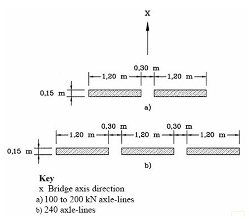
Thus when the vehicle placements
corresponding to the Standardised LM3 and the UK LM3 are
visualized using the Moving Load Tracer, the transverse
wheel spacing is same as defined in the lanes definition.
But this is not the actual transverse wheel spacing corresponding
to the straddling vehicles( UK LM3 vehicles).The transverse
wheel spacing for straddling SV and SOV as defined in
UK National Annex is shown below. Thus to consider the
effects of UK LM3 vehicle with the actual wheel spacing,
the obtained results from the Moving Load Tracer are converted
into static Load using ![]() and the program automatically considers the below mentioned
spacings in the converted static loads and thus the results
obtained using the converted static loads reflect the
results corresponding to the true wheel spacings.
and the program automatically considers the below mentioned
spacings in the converted static loads and thus the results
obtained using the converted static loads reflect the
results corresponding to the true wheel spacings.
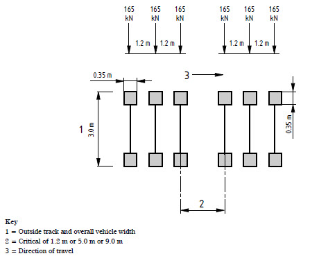
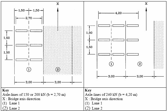
The transverse wheel spacing for LM3 SV 100(same for other SVs ): 2.65m centre-centre.
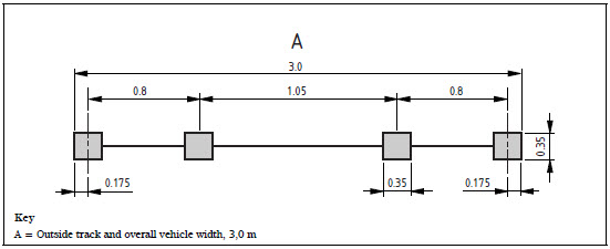
The transverse wheel spacing for LM3 SOV vehicles.
Note2
Vehicle Placement :When the LM3 vehicles are applied alone, they are applied in the manner shown below. Any LM3 vehicles having three wheels per axle shown in the right side of the image are not supported. This placement applies to only the standardised Load Model 3 vehicles. A load case considering when the placement of LM3 vehicles when applied in isolation is considered using the LM 2,3,4/ FLM 2,3,4/ Footbridge load model in Moving Load cases (Refer to Moving Load Cases). The Standard LM3 vehicles cannot be applied in two lanes so the right hand vehicle placement in the image shown below cannot be achieved. The straddling effect or the placement of vehicle in two lanes can be accounted for the straddling vehicles only by specifying the LM1 & 3( special) Load model in Moving Load cases (Refer to Moving Load cases).
Note3
Dynamic Amplification Factor:The value of characteristic loads for Load Models 1,2 and 4 includes the dynamic amplification consideration. But for Load Model 3 special vehicles this dynamic amplification factor needs to be considered separately as it is not included in the axle loads. The dynamic amplification factor can be input manually or calculated automatically by the program.
When the vehicle is recommended Load Model 3 vehicle: Dynamic Amplification Factor calculated by the program is considered based on the equation given below.

DAF for recommended Load Model 3 vehicles
When the vehicle is Load Model 3 as per UK NA: Dynamic Amplification Factor calculated by the program is considered corresponding to the basic axle loads as shown below
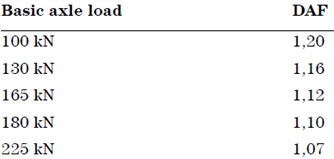
DAF for UK Load Model 3 vehicles
In case of Load Model 3, additional dynamic amplification factor within a distance of 6 m from an expansion joint is not considered.
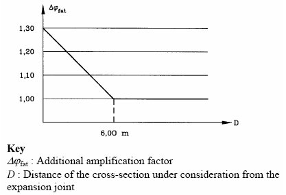
Representation of the additional amplification factor
![]() EN1991-2:2003
- Footway and Foot Bridge
EN1991-2:2003
- Footway and Foot Bridge
Enter the Load Model acting on Footway or Foot Bridge. For details on input parameters, refer to Section 5.3 in 'Eurocode 1: Action on structures - Part 2 : Traffic loads on bridges'.
![]() EN1991-2:2003
- Road bridge Fatigue
EN1991-2:2003
- Road bridge Fatigue
Enter the Fatigue Load Model for Road Bridge. For details on input parameters, refer to Section 4.6 in 'Eurocode 1: Action on structures - Part2: Traffic loads on Bridges.'
![]() EN1991-2:2003
- Rail Traffic Load
EN1991-2:2003
- Rail Traffic Load
The Rail Traffic Loads as per EN 1991-2:2003 can be specified. The various load models considered in the program are:
Load Model 71 (and Load Model SW/0 for continuous bridges) to represent normal rail traffic on mainline railways,
Load Model SW/2 to represent heavy loads,
Load Model HSLM A/B to represent the loading from passenger trains at speeds exceeding 200 km/h. Dynamic amplification is also considered.
Load Model "Unloaded train" to represent the effect of an unloaded train.
Longitudinal distribution of a point force or wheel load by the rail
A point force in Load Model 71 and HSLM A(A1 to A10) may be distributed over three rail support points as shown below:
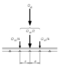
where :
Qvi: point force on each rail due to load model 71 and HSLM A.
a: distance between rail support points.
Figure 1. Longitudinal distribution of point load
Eccentricity of Lateral Displacement of Vertical Loads
According to the clause 6.3.5 of EN 1991-2, the effect of lateral displacement of vertical loads (unbalanced or asymmetric loading of wagons) needs to be considered by taking the ratio of wheel loads on all axles as up to 1.25:1.0 on any one track. This criterion may be used to determine the eccentricity of loading with respect to the center-line of the track.
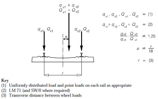
Figure 2. Eccentricity of vertical loads
Note 1
Sign convention of eccentricity: The positive value means that the sum of vertical loads is applied to the right side of the train by the amount of eccentricity with respect to the center of gravity.
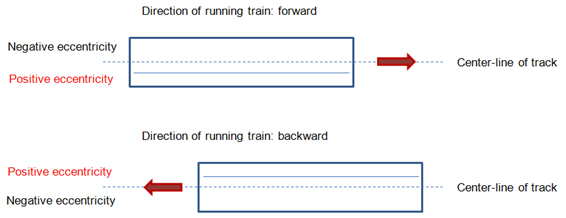
Figure 3. Sign convention of eccentricity
Note 2
How to consider the effect of lateral displacement of LM 71 on one track only:
Suppose there are two tracks named ‘L1’ and ‘L2’ and we want to consider this effect only for the track ‘L1’.
Step 1 Define two LM71 models- one with eccentricity (LM 71E) and the other without eccentricity (LM 71).
Step 2 In the Moving Load Case, create two sub-load cases as follows:
Sub-load case 1: Select the train ‘LM 71E’ and the track ‘L1’.
Sub-load case 2: Select the train ‘LM 71’ and the track ‘L2’.
Step 3 Select the ‘Combined’ option for Loading Effect
Dynamic effect
For HSLM (A1- A10) and HSLM B, a dynamic enhancement is applied as per the factor obtained from the equation below where the value of phi' and phi" are input by the user. This dynamic factor amplifies the static load accordingly but this is very different from the dynamic analysis which needs to be performed separately if the dynamic behavior of the bridge with the vehicle motion has to be considered.

 AS
5100.2 - Road Traffic
Enter the vehicle loads specified in AS 5100.2 specification.
W80, A160, M1600, M1600 without UDL, M1600 tri-axle group, S1600
Note: A160 and M1600 without UDL can be applied to the fatigue moving load case.
 Pedestrian and Bicycle-path Load
Enter the vehicle loads specified in AS 5100.2 specification.
Attached to Road Bridge, Independent of Road Bridge, Service Live Load on Walkways
 AS 5100.2 - Rail Traffic Load
Vehicular Load Type
150LA, 300LA
Dynamic Load Allowance
The design action is equal to (1+alpha) x the load factor x the action under consideration. Enter the value corresponding to alpha. Dynamic load allowance (alpha) can be applied separately between bending moment and all other effects. Characteristic length is not automatically determined by the program. Dynamic load allowance (alpha) should be directly defined by the user.
Bending Moment: Enter dynamic load allowance to be applied to bending moments, i.e. My, Mz
All Other Effects: Enter dynamic load allowance to be applied to all other effects, i.e. axial force, shear force, torsion, displacements.
Note:
1. Different dynamic load allowances between bending moment and all other effects can be applied to beam element and virtual beam only. For all other type of elements including plate element, the value entered for all other effects will be applied.
2. Composite Section for C.S has both total section forces and part forces. Different dynamic load allowances between bending moment and all other effects will be applied on the basis of total section forces. The part forces provided from the Result Tables>Composite Section for C.S>Beam Force will be the results to which the dynamic load allowance for all other effects is applied.
3. Bending stresses are calculated using the dynamic load allowance for bending moment. Axial stresses are calculated using the dynamic load allowance for all other effects. Note that combined stresses will be calculated using the dynamic load allowance for all other effects. Thus it will not be equal to the sum of axial stress and bending stress. In the moving load analysis, stresses are determined on the basis of the influence line of individual stress, i.e. axial stress, bending stress, combined stress.
 AS 5100.2 - Heavy Load Platform
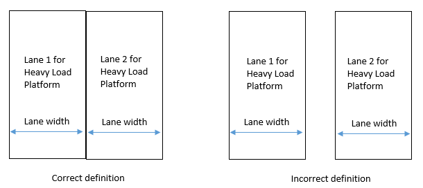
The HLP 320 and HLP 400 heavy load platform shall be positioned within two standard design lanes. The Heavy Load Platform shall be positioned up to 1.0 m laterally from the center of two standard design lanes to create the worst effect. Note that these two lanes should be adjacent and the two lanes should not be away from each other. The two adjacent lanes should meet each other at the boundary lines of the lane width.
Vehicular Load Type
HLP 320, HLP 400
Dynamic Load Allowance
The design action is equal to (1+alpha) x the load factor x the action under consideration. Enter the value corresponding to alpha. The recommended value for heavy load platform is 0.1.
 AS 5100.7 - Rating Vehicles
Vehicular Load Type
T44 Truck Load, L44 Lane Load
Dynamic Load Allowance
The design action is equal to (1+alpha) x the load factor x the action under consideration. Enter the value corresponding to alpha. The recommended value for rating vehicles is 0.4.
Enter the vehicle loads specified in the IRC:6-2000 standard.
 IRS Bridge Rules
Enter the vehicle loads specified in IRS Bridge Rules.
Enter the vehicle loads specified in Taiwan standard.
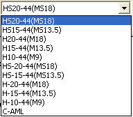
Select the vehicles for moving load analysis as per Russian Moving Load Code. The following vehicles can be selected for performing the moving load analysis.
Standard Name
Road Bridge and Railway Bridge:
SP 35.13330.2011 : SK, AK, N11, N14, Subway and Tramcars
SNiP 2.05.03-84 : NG-60 and NK-80
Walkway and Pedestrian loads:
SP 35.13330.2011 : Uniform loads, Concentrated loads with and without AK.
Vehicular Load Properties
AK, SK, SK Fatigue, N14 and N11: The AK, SK, SK Fatigue, N14 and N11 vehicles as defined in the SP 35.13330.2011 contains a multiplier factor (K), which determines the axle load (and in turn the wheel) for moving load analysis.
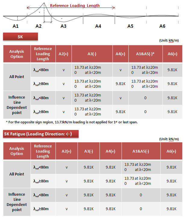
Note. Application of SK and SK Fatigue
Normative temporary vertical load, SK, applied by the railroad rolling stock is applied as shown in the example below. The application of loading is changed based on the Load Point Section: Influence Line Dependent Point/ All Point option in the Moving load Analysis Control dialog box.
When the influence line is shown as below, for the maximum bending moment:
![]() Load Factor (K)
Load Factor (K)
Define the load factor K for the determination of axle load for the moving load analysis. The factor K is multiplied to the following when the units for the loads are KN:
AK: 10
SK: 9.81 or 13.73 depending on the value of Influence Load Length (λ)
N11: 14
N14: 18
For all other units a conversion is made from KN to obtain the factor to be multiplied to K to obtain the axle load. Default value of K is 14. The value of Axle load (or the wheel load) can be verified from the Moving Load Tracer.
![]() Dynamic Factor
Dynamic Factor
The dynamic factor can be defined automatically as per the code or manually by the user. The applied dynamic factor can be checked in the moving load tracer, Detail Results text output.
The dynamic load factors can be defined in the Vehicle definition dialog box.
The displayed material and bridge type can be changed from Moving Load Analysis Control.
Automatic Definition of Dynamic Factor: The dynamic factor is defined as per the material ( RC , Steel and SRC) and the type of bridge.
The type of material and bridge can be defined in Moving Load Analysis Control.
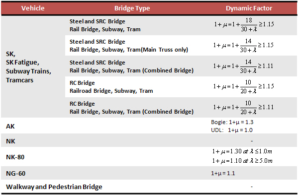
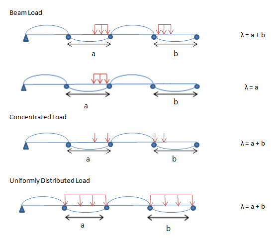
The automatic dynamic factor calculation involves the Influence Load Length (λ)
The following procedure is adopted in midas civil for the calculation of λ:
Manual Definition of Dynamic Factor: The dynamic factor can be defined manually for UDL and Concentrated Loads individually.
Select the vehicles for moving load analysis as per Polish Moving Load Code. The following vehicles can be selected for performing the moving load analysis.
![]() Standard
Name
Standard
Name
PN-85/S-10030 - Road Bridge
Vehicle K, Vehicle S, Vehicle 2S
PN-85/S-10030 - Walkway and Pedestrian Bridge
Sidewalks/stairs and walkways, Main girders and supports, Service walkways and working platforms
Military Load Class
Tracked vehicle, Wheeled vehicle according to TRILATERAL DESIGN AND TEST CODE FOR MILITARY BRIDGING AND GAP-CROSSING EQUIPMENT (2005)
![]() Vehicular
Load Properties
Vehicular
Load Properties
Vehicle K, Vehicle S and Vehicle 2S: Vehicle K, Vehicle S and Vehicle 2S as defined in the PN-85/S-10030 contains a dynamic amplification factor, which determines the axle load for moving load analysis.
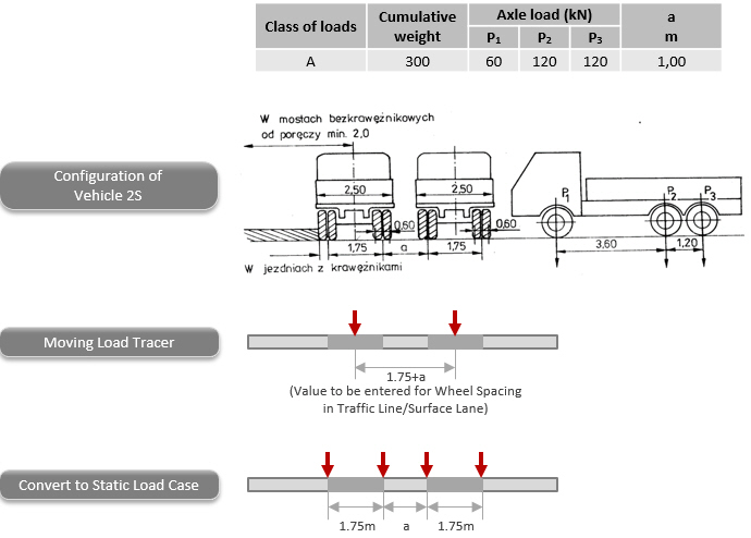
Note. Application of Vehicle 2S
Limitation for vehicle 2S:
One axle of Vehicle 2S consists of 4 wheels. In the program, only two wheels are allowed in one axle. Therefore, the wheel spacing in Traffic Line/Surface Lane dialog box should be entered considering the distance between the center lines of two trucks. In moving load tracer, the wheel loads will be placed to the center line of each truck for all the axles. However, the user can convert this loadings into a static load case in which actual positions of 4 wheels are taken into account.
Dynamic Amplification Factor
PN-85/S-10030 : Sidewalks/stairs and walkways, Main girders and supports, Service walkways and working platforms
The dynamic factor can be defined automatically as per the code or manually by the user. The applied dynamic factor is not reflected in the wheel load value in the moving load tracer, however it is reflected in the analysis results such as member forces/stresses, displacements and reactions. Dynamic amplification factor can automatically be calculated considering span length. For multi-span bridges, average span length is applied as specified in Polish Standard. Span length can automatically be calculated using “Span Start” option in Traffic Line/Surface Lane dialog box.
Auto: The dynamic factor is defined as per the code.
Phi = 1.35 - 0.005L (unit: meter)
1.00 ≤ Phi ≤ 1.325
User Input: The dynamic factor can be defined manually for Concentrated Loads.
Note. Military Load Class
Tracked Vehicle, Wheeled Vehicle
Application Rule
 TMH7 Standard Load
Vehicular Load Name: Enter the name of the vehicular load.
Vehicular Load Type: Select the type of the vehicular load.

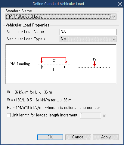
NA (Normal Loading)
The load to be applied depends on Effective Loaded Length and Increment of Loaded Length. It does not depend on the lane order.
The loaded length causing the worst effect can be in other lane, either parallel on the same span or in the other span as the case may be.
NA loading represents normal traffic loading and comprises of 2 parts acting simultaneously:
i) Nominal distributed lane loading:
![]()
W
= Average load per meter of Notional Lane (kN)
L
= Effective loaded length (m)
Above
equation is valid for L>36m, for L ≤ 36m → W
= 36kN/m
ii) Nominal axle load:
Load
per notional lane = ![]()
n = Notional lane number
Note
Engineering judgement is required whether to consider the relieving effect (opposing effect) of the vehicle or not.
NB (Abnormal Loading)
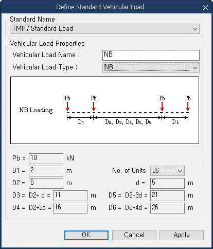
NB loading is a unit loading representing a single abnormally heavy vehicle. Type NB vehicle has no specified load lane and can be placed anywhere in carriage way. NB24 and NB36 vehicles can be selected by selecting the no. of units. 36 units of type NB loading shall be applied, which equals an axle loading of 360 kN and 24 units of type NB loading shall be applied, which equals an axle loading of 240 kN.
Load Calculation for Type NB Vehicle:
The plan and axel arrangement of Unit NB vehicle is as below:
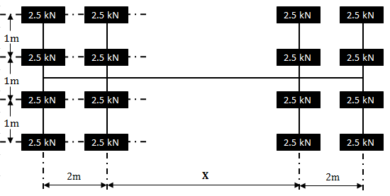
X
is automatically decided such that the effect is worst for
the element under consideration.
Allowable
values of X are 6, 11, 16, 21 and 26m. Load of above mentioned
vehicle is multiplied with appropriate unit.
There are 2 codal magnitudes for Type NB Vehicle:
i) Type NB36 Loading:
Unit NB vehicle shold be multiplied with 36.
Load for each wheel = 36 (unit) x 2.5 (kN) = 90kN
Load for each axel = 36 (unit) x 4 (wheels) x 2.5 (kN) = 360kN
ii) Type NB24 Loading:
Unit NB vehicle shold be multiplied with 24.
Load for each wheel = 24 (unit) x 2.5 (kN) = 60kN
Load for each axel = 24 (unit) x 4 (wheels) x 2.5 (kN) = 240kN
NC (Super Loading)
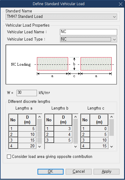
NC loading is a loading representing multi-wheeled trailer combinations (or self-propelled multi-wheeled vehicles) with controlled hydraulic suspension and steering intended to transport very heavy indivisible payloads. NC vehicle has no specified load lane and has to be placed near the center of carriageway with a maximum offset up to 1m unless otherwise specified.
Type
NC vehicle consists of loaded areas only.
a : Length of loaded area
b : Width of loaded area
c
: Length of area
not loaded
The
allowable values of a, b and c are as below:
a : 5m, 10m, 15m, 20m
b : 3m, 4m, 5m
c : 0m, 5m, 10m, 15m, 20m,
25m
Intensity of load in the loaded area is 30 kN/m2. This load is an area load and needs to be converted into UDL in accordance to the placement and distribution method (Cross Beam or Lane Element).
Note
Engineering judgement is required whether to consider the relieving effect (opposing effect) of the vehicle or not.
Click
![]() when the user directly enters the vehicle load.
when the user directly enters the vehicle load.
 Load type
Enter the type of vehicle loads
Truck / Lane: Concentrated axle loads or traffic lane loads
Train Load: Train Loads
 Vehicular Load Properties
Vehicular
Name
Enter the name of a vehicle.
Truck Load
Enter the concentrated wheel axle loads and spacings.
P#: Concentrated loads
D#: Spacings between concentrated loads
![]() : Add the
entered concentrated loads.
: Add the
entered concentrated loads.
![]() : Insert
a concentrated load at a specified position.
: Insert
a concentrated load at a specified position.
![]() : Modify
the magnitude or spacing of the concentrated loads previously
selected in the list.
: Modify
the magnitude or spacing of the concentrated loads previously
selected in the list.
![]() : Delete
the selected loads from the list of previously entered concentrated
loads.
: Delete
the selected loads from the list of previously entered concentrated
loads.
Note
The data
entry sequence
for
the
wheel loads must coincide with the actual moving sequence of the wheels.
Lane
Load
Enter traffic lane loads.
w: Distributed traffic lane load
PL: Concentrated traffic lane load used to calculate member forces
PLM: Concentrated traffic lane load used for moment calculations
PLV: Concentrated traffic lane load used for shear force calculations
Train
Load
Enter subway train loads.
dW1~2: Distributed traffic lane load
dD1~2: Spacing between the distributed traffic lane load and concentrated load (Refer to diagram)
P: Concentrated traffic lane load (Enter in Load)
D: Spacing between concentrated traffic loads (Enter in Distance)
Vehicular Load Name: Enter the name of the vehicular load.
Type of Axle
Name: Enter the name of the axle
Evenly Distributed Wheel Load: By selecting this option, all loads, except P1, are deactivated and the program uses P1 for analysis.
Symmetric Vehicle: By selecting this option, the program only uses the wheel loads right-side of the vehicle for analysis.
P1, P2, ..., Pn: Enter the wheel loads of each axle. Enter the wheel load starting from the wheel closest to the center.
D1, D2, ..., Dn: Enter the distance between the center to the wheel. Indicate right side as (+) and left side as (-).
Table: Enter the vehicle load using the defined axle.
Type of Axle: Select the defined axle.
VS: Variable spacing. [Details]
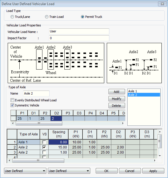
VS represents the variable spacing of axle in longitudinal direction as required for certain Permit Truck user defined vehicle. VS option can’t be activated for the first axle. When VS is activated for any axle, the axles are placed in accordance to the influence line diagram. The minimum distance is the spacing as entered in the preceding axle and maximum spacing is spacing as entered in the axle for which VS is checked on. In case of the example above, the spacing between Axle 1 and Axle 2 is variable from 0.5m to 15m and the 3rd axle is placed 1m after the second axle.
Spacing: Enter the distance between the axles.
When Truck/Lane is selected
Vehicular
Name
Enter the name of a vehicle.
Truck Load
Enter the concentrated wheel axle loads and spacings.
P#: Concentrated loads
D#: Spacings between concentrated loads
![]() : Add the
entered concentrated loads.
: Add the
entered concentrated loads.
![]() : Insert
a concentrated load at a specified position.
: Insert
a concentrated load at a specified position.
![]() : Modify
the magnitude or spacing of the concentrated loads previously
selected in the list.
: Modify
the magnitude or spacing of the concentrated loads previously
selected in the list.
![]() : Delete
the selected loads from the list of previously entered concentrated
loads.
: Delete
the selected loads from the list of previously entered concentrated
loads.
Note
The data
entry sequence
for
the
wheel loads must coincide with the actual moving sequence of the wheels.
Lane
Load
Enter traffic lane loads.
w: Distributed traffic lane load
Dynamic Load Allowance
Auto: Apply Dynamic Load Allowance factor as per Canadian specification
User Input: Apply Dynamic Load Allowance factor using user input value
As specified in the code, it is differently applied for the following condition.
Where only one axle of the CL-W Truck is used
Where any two axle or axles 1,2 and 3 are used
Where three axles except for axles 1,2 and 3 or more than three axles are used
Note
The applied dynamic load allowance factor can be checked by lanes in the moving load tracer by clicking [Detail Results] button.
When "Permit Truck" is selected
Name: Enter the name of the axle
Evenly Distributed Wheel Load: By selecting this option, all loads, except P1, are deactivated and the program uses P1 for analysis.
Symmetric Vehicle: By selecting this option, the program only uses the wheel loads right-side of the vehicle for analysis.
P1, P2, ..., Pn: Enter the wheel loads of each axle. Enter the wheel load starting from the wheel closest to the center.
D1, D2, ..., Dn: Enter the distance between the center to the wheel. Indicate right side as (+) and left side as (-).
Table: Enter the vehicle load using the defined axle.
Type of Axle: Select the defined axle.
Spacing: Enter the distance between the axles.
 HA
& HB (BS5400) Loading
Enter the vehicle loads specified in BS5400 Standard.
 HA Loading
Enter HA vehicle loads specified in BD37/01 Standard. HA Lane Factor can be considered with the value calculated by the program or defined by the user.
 HB Loading
Enter HB vehicle loads specified in BD37/01 Standard.
![]() HA & HB Loading
HA & HB Loading
Enter HA and HB loading combined in one lane specified in BD37/01 Standard. HA UDL in a lane shall be loaded to the total length displaced by HB loading with the front and rear clear spaces (dd).
HA Lane Factor can be considered with the value calculated by the program or defined by the user.
![]() HA
& HB (Auto) Loading
HA
& HB (Auto) Loading
Enter HA and HB loading combined for the entire lanes so that the program can automatically organize live load combination specified in BD37/01 Standard as shown in the figures below.
HA loading shall be applied to the notional lanes of the carriageway. HA UDL and KEL shall be multiplied by the lane factor. HB loading shall occupy any transverse position on the carriage way, either wholly within one notional lane or straddling two notional lanes.

HB Vehicle within One Lane

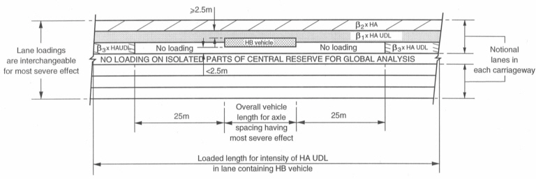
HB Vehicle Straddling Two Lanes
 Pedestrian Live Load
Enter foot/cycle track bridge live loads specified in BD37/01 Standard.
 Permit
Truck
Vehicular Load Name: Enter the name of the vehicular load.
Impact Factor: This refers to the portion of dynamic effect due to moving vehicles. This should not include the static effect of vehicle loads. Thus, this factor is usually less than 1.0.
Type of Axle
Name: Enter the name of the axle
Evenly Distributed Wheel Load: By selecting this option, all loads, except P1, are deactivated and the program uses P1 for analysis.
Symmetric Vehicle: By selecting this option, the program only uses the wheel loads right-side of the vehicle for analysis.
P1, P2, ..., Pn: Enter the wheel loads of each axle. Enter the wheel load starting from the wheel closest to the center.
D1, D2, ..., Dn: Enter the distance between the center to the wheel. Indicate right side as (+) and left side as (-).
Table: Enter the vehicle load using the defined axle.
Type of Axle: Select the defined axle.
Spacing: Enter the distance between the axles.
![]() EN1991-2:2003 - Road Bridge/Footway
and Foot Bridge
EN1991-2:2003 - Road Bridge/Footway
and Foot Bridge
The user can directly enter the vehicle load data such as magnitudes of vehicle loads, distance between wheels and other parameters.
Various Load Models as per EN1991-92 can be defined here. These Load Models include:
Load Model 1 / Fatigue Load Model 1: Concentrated and uniformly distributed loads, which cover most of the effects of the traffic of lorries and cars.
Note
In Fatigue Load Model, Φ1 Factor applies to One Vehicle
and Φ2 Factor applies to First Vehicle and Second Vehicle
simultaneously in Two Vehicle considered cases.
Load Model 2, 4 / Fatigue Load Model 2, 4: Concentrated and uniformly distributed loads.
Load Model 3: A set of assemblies of axle loads representing special vehicles (e.g. for industrial transport) which can travel on routes permitted for abnormal loads. Application of special vehicles refer to EN1991-2-Annex A. A load case considering the placement of LM1 and recommended LM3 vehicles can be specified by selecting the LM1 & 3( multi) load model in Moving Load cases (Refer to Moving Load Cases). The most unfavorable result is produced by considering the entered three Load Cases.
Load Model 3 (Straddling): The special vehicles as per UK national annex can straddle between two lanes by the program. For description about the notations and axle loadings and spacings refer to UK National Annex to Eurocode1:Actions on structures.
Note Load Model3 (Straddling)
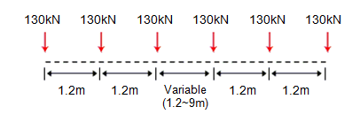
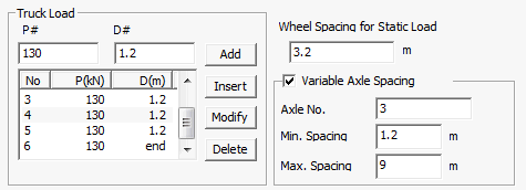
Load Model3 (Straddling) vehicle can be considered with variable axile spacing. For example, if the vehicle is composed as shown in the figure below, the variable axle spacing can be specified by entering Axle No. and Min/Max axle spacings. For the last axle, the user needs to specify the spacing "D#" as "0", so that it can be considered as "end" spacing.
Wheel spacing during an analysis will be applied as the spacing defined in Traffic Line Lanes/Traffic Surface Lanes. If the wheel spacing is different from the one defined in Traffic Line Lanes/Traffic Surface Lanes, exact wheel spacing can be considered by converting the vehicle loads into static loads using "Write Min/Max Load to File" button in Moving Load Tracer.
Permit Truck
Evenly Distributed Wheel Load: By selecting this option, all loads, except P1, are deactivated and the program uses P1 for analysis.
Symmetric Vehicle: By selecting this option, the program only uses the wheel loads right-side of the vehicle for analysis.
P1, P2, ..., Pn: Enter the wheel loads of each axle. Enter the wheel load starting from the wheel closest to the center.
D1, D2, ..., Dn: Enter the distance between the center to the wheel. Indicate right side as (+) and left side as (-).
Table: Enter the vehicle load using the defined axle.
Type of Axle: Select the defined axle.
Spacing: Enter the distance between the axles.
Note1
Wheel Spacings for the Recommended LM3 vehicles and UK LM3 vehicles
In case of Load Model 3 vehicles, the transverse wheel spacing considered is the value of the wheel spacings that has been entered while defining the lanes. Therefore when the Load Model 3 vehicles are used in combination with the Load Model 1 vehicles or in isolation, the same transverse wheel spacings are considered both for the LM3 and LM1 vehicles. In case of Recommended Load Model 3, three wheels at one axle (figure b) are converted into equivalent two wheel loads when placed in combination with Load Model vehicle or when used in isolation. Therefore for any Recommended Load Model 3 vehicle the effect due to the true transverse spacings between the wheels could not be captured but rather the effect due to equivalent two wheels is captured.

Thus when the vehicle placements
corresponding to the Standardised LM3 and the UK LM3 are
visualized using the Moving Load Tracer, the transverse
wheel spacing is same as defined in the lanes definition.
But this is not the actual transverse wheel spacing corresponding
to the straddling vehicles( UK LM3 vehicles).The transverse
wheel spacing for straddling SV and SOV as defined in
UK National Annex is shown below. Thus to consider the
effects of UK LM3 vehicle with the actual wheel spacing,
the obtained results from the Moving Load Tracer are converted
into static Load using ![]() and the program automatically considers the below mentioned
spacings in the converted static loads and thus the results
obtained using the converted static loads reflect the
results corresponding to the true wheel spacings.
and the program automatically considers the below mentioned
spacings in the converted static loads and thus the results
obtained using the converted static loads reflect the
results corresponding to the true wheel spacings.

The transverse wheel spacing for LM3 SV 100(same for other SVs ): 2.65m centre-centre.

The transverse wheel spacing for LM3 SOV vehicles.
Note2
Vehicle Placement :When the LM3 vehicles are applied alone, they are applied in the manner shown below. Any LM3 vehicles having three wheels per axle shown in the right side of the image are not supported. This placement applies to only the standardised Load Model 3 vehicles. A load case considering when the placement of LM3 vehicles when applied in isolation is considered using the LM 2,3,4/ FLM 2,3,4/ Footbridge load model in Moving Load cases (Refer to Moving Load Cases). The Standard LM3 vehicles cannot be applied in two lanes so the right hand vehicle placement in the image shown below cannot be achieved. The straddling effect or the placement of vehicle in two lanes can be accounted for the straddling vehicles only by specifying the LM1 & 3( special) Load model in Moving Load cases (Refer to Moving Load cases).

Note3
Dynamic Amplification Factor:The value of characteristic loads for Load Models 1,2 and 4 includes the dynamic amplification consideration. But for Load Model 3 special vehicles this dynamic amplification factor needs to be considered separately as it is not included in the axle loads. The dynamic amplification factor can be input manually or calculated automatically by the program.
When the vehicle is recommended Load Model 3 vehicle: Dynamic Amplification Factor calculated by the program is considered based on the equation given below.

DAF for recommended Load Model 3 vehicles
When the vehicle is Load Model 3 as per UK NA: Dynamic Amplification Factor calculated by the program is considered corresponding to the basic axle loads as shown below

DAF for UK Load Model 3 vehicles
In case of Load Model 3, additional dynamic amplification factor within a distance of 6 m from an expansion joint is not considered.

Representation of the additional amplification factor
![]() EN1991-2:2003
- Rail Traffic Load
EN1991-2:2003
- Rail Traffic Load
The Rail Traffic Loads as per EN 1991-2:2003 can be specified. The various load models considered in the program are:
Load Model 71 (and Load Model SW/0 for continuous bridges) to represent normal rail traffic on mainline railways,
Load Model SW/2 to represent heavy loads,
Load Model HSLM A/B to represent the loading from passenger trains at speeds exceeding 200 km/h. Dynamic amplification is also considered.
Load Model "Unloaded train" to represent the effect of an unloaded train.
Longitudinal distribution of a point force or wheel load by the rail
A point force in Load Model 71 and HSLM A(A1 to A10) may be distributed over three rail support points as shown below:

where :
Qvi: point force on each rail due to load model 71 and HSLM A.
a: distance between rail support points.
Figure 1. Longitudinal distribution of point load
Eccentricity of Lateral Displacement of Vertical Loads
According to the clause 6.3.5 of EN 1991-2, the effect of lateral displacement of vertical loads (unbalanced or asymmetric loading of wagons) needs to be considered by taking the ratio of wheel loads on all axles as up to 1.25:1.0 on any one track. This criterion may be used to determine the eccentricity of loading with respect to the center-line of the track.

Figure 2. Eccentricity of vertical loads
Note 1
Sign convention of eccentricity: The positive value means that the sum of vertical loads is applied to the right side of the train by the amount of eccentricity with respect to the center of gravity.

Figure 3. Sign convention of eccentricity
Note 2
How to consider the effect of lateral displacement of LM 71 on one track only:
Suppose there are two tracks named ‘L1’ and ‘L2’ and we want to consider this effect only for the track ‘L1’.
Step 1 Define two LM71 models- one with eccentricity (LM 71E) and the other without eccentricity (LM 71).
Step 2 In the Moving Load Case, create two sub-load cases as follows:
Sub-load case 1: Select the train ‘LM 71E’ and the track ‘L1’.
Sub-load case 2: Select the train ‘LM 71’ and the track ‘L2’.
Step 3 Select the ‘Combined’ option for Loading Effect
Dynamic effect
For HSLM (A1- A10) and HSLM B, a dynamic enhancement is applied as per the factor obtained from the equation below where the value of phi' and phi" are input by the user. This dynamic factor amplifies the static load accordingly but this is very different from the dynamic analysis which needs to be performed separately if the dynamic behavior of the bridge with the vehicle motion has to be considered.

 Truck/Lane
Enter the vehicle loads for truck and lane loads.
Variable Spacing (D6~D7): Check on the variable spacing option to simulate M1600 and S1600 vehicles. When this option is checked on, the value entered in "D6" will be applied as the minimum variable spacing, and the value entered in "D7" will be automatically changed to infinite length in order to find the most critical axle spacing.
 Train Load
Enter the distributed loads such as pedestrian and bicycle-patch loads.
 Railway Traffic Load
Enter user-defined 300LA and 150LA loads. When 150LA is defined from the Standard vehicle, the number of axle groups is fixed as 2. When 150LA is defined from the User-Defined vehicle, the number of axle groups can be defined by the user. Also, locomotive load can be removed.
Dynamic Load Allowance
Dynamic load allowance (alpha) can be applied separately between bending moment and all other effects. Characteristic length is not automatically determined by the program. Dynamic load allowance (alpha) should be directly defined by the user.
Bending Moment: Enter dynamic load allowance to be applied to bending moments, i.e. My, Mz
All Other Effects: Enter dynamic load allowance to be applied to all other effects, i.e. axial force, shear force, torsion, displacements.
Note:
1. Different dynamic load allowances between bending moment and all other effects can be applied to beam element and virtual beam only. For all other type of elements including plate element, the value entered for all other effects will be applied.
2. Composite Section for C.S has both total section forces and part forces. Different dynamic load allowances between bending moment and all other effects will be applied on the basis of total section forces. The part forces provided from the Result Tables>Composite Section for C.S>Beam Force will be the results to which the dynamic load allowance for all other effects is applied.
3. Bending stresses are calculated using the dynamic load allowance for bending moment. Axial stresses are calculated using the dynamic load allowance for all other effects. Note that combined stresses will be calculated using the dynamic load allowance for all other effects. Thus it will not be equal to the sum of axial stress and bending stress. In the moving load analysis, stresses are determined on the basis of the influence line of individual stress, i.e. axial stress, bending stress, combined stress.
 Permit Truck
Vehicular Load Name: Enter the name of the vehicular load.
Impact Factor: This refers to the portion of dynamic effect due to moving vehicles. This should not include the static effect of vehicle loads. Thus, this factor is usually less than 1.0.
Type of Axle
Name: Enter the name of the axle
Evenly Distributed Wheel Load: By selecting this option, all loads, except P1, are deactivated and the program uses P1 for analysis.
Symmetric Vehicle: By selecting this option, the program only uses the wheel loads right-side of the vehicle for analysis.
P1, P2, ..., Pn: Enter the wheel loads of each axle. Enter the wheel load starting from the wheel closest to the center.
D1, D2, ..., Dn: Enter the distance between the center to the wheel. Indicate right side as (+) and left side as (-).
Table: Enter the vehicle load using the defined axle.
Type of Axle: Select the defined axle.
Spacing: Enter the distance between the axles.
![]() When the user selects the Wheeled/Tracked/Bogie option
When the user selects the Wheeled/Tracked/Bogie option
The user can define vehicles, including class 60R and others, and assign the defined vehicles to Class II.
Note
midas Civil considers two classes of vehicles to define the Live Load Combinations. Class AA, Class 70R and Class 40R are classified into Class II, and Class A and Class B are classified into Class I.
![]() When the user selects the Wheeled option
When the user selects the Wheeled option
The user can define vehicles and assign these to Class I.
![]() When
"Permit Truck" is selected
When
"Permit Truck" is selected
Name: Enter the name of the axle
Evenly Distributed Wheel Load: By selecting this option, all loads, except P1, are deactivated and the program uses P1 for analysis.
Symmetric Vehicle: By selecting this option, the program only uses the wheel loads right-side of the vehicle for analysis.
P1, P2, ..., Pn: Enter the wheel loads of each axle. Enter the wheel load starting from the wheel closest to the center.
D1, D2, ..., Dn: Enter the distance between the center to the wheel. Indicate right side as (+) and left side as (-).
Table: Enter the vehicle load using the defined axle.
Type of Axle: Select the defined axle.
Spacing: Enter the distance between the axles.
Note
IRC Class Special Vehicle (SV) can be selected as shown below.
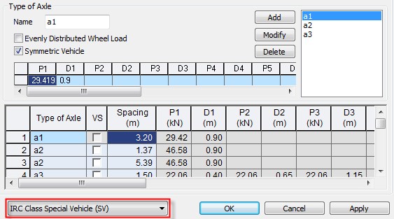
![]() Vehicular Load Properties
Vehicular Load Properties
Vehicular Name
Enter the name of a vehicle.
Vehicular Load Type
Enter the vehicular load type for automatic determination of the Lane factor
Truck Load
Enter the concentrated wheel axle loads and spacings.
P#: Concentrated loads
D#: Spacings between concentrated loads
![]() : Add the
entered concentrated loads.
: Add the
entered concentrated loads.
![]() : Insert
a concentrated load at a specified position.
: Insert
a concentrated load at a specified position.
![]() : Modify
the magnitude or spacing of the concentrated loads previously
selected in the list.
: Modify
the magnitude or spacing of the concentrated loads previously
selected in the list.
![]() : Delete
the selected loads from the list of previously entered concentrated
loads.
: Delete
the selected loads from the list of previously entered concentrated
loads.
Min D4 Variable: This option is activated when the vehicular load type is specified as Tramcars. D4 can be defined for defining the minimum spacing between the tram loading for determining the position of the vehicle for obtaining the worst effect.
Note 1. Important Notice for User Defined Subway Trains
The data entry sequence for the wheel loads must coincide with the actual moving sequence of the wheels. The number of concentrated loads must be 4 in order to represent one subway train. And then, the program automatically consider unlimited trains as specified in the Russian Standard.
Note 2. Important Notice for User Defined Tramcars
The data entry sequence for the wheel loads must coincide with the actual moving sequence of the wheels. The number of concentrated loads must be 4 in order to represent one tramcar. And then, the program automatically consider 4 tram cars as specified in the Russian Standard.
Lane Load
Enter traffic lane loads.
w: Distributed traffic lane load
![]() Dynamic Factor
Dynamic Factor
Auto- Calculation
For the user defined vehicles the automatic calculation of Dynamic factor is allowed only for Subway Trams, N14, NK 80 vehicles. The type of bridge and material can be defined in moving load analysis control.
User Input
Dynamic Factor for Bogie: Enter the dynamic load factor to be applied to concentrated ( Tuck ) Loads
Dynamic Factor for UDL: Enter the dynamic factor to be applied to Lane Load.

The automatic dynamic factor calculation involves the Influence Load Length (λ)
The following procedure is adopted in midas Civil for the calculation of λ:

Vehicular Load Name: Enter the name of the vehicular load.
Type of Axle
Name: Enter the name of the axle
Evenly Distributed Wheel Load: By selecting this option, all loads, except P1, are deactivated and the program uses P1 for analysis.
Symmetric Vehicle: By selecting this option, the program only uses the wheel loads right-side of the vehicle for analysis.
P1, P2, ..., Pn: Enter the wheel loads of each axle. Enter the wheel load starting from the wheel closest to the center.
D1, D2, ..., Dn: Enter the distance between the center to the wheel. Indicate right side as (+) and left side as (-).
Table: Enter the vehicle load using the defined axle.
Type of Axle: Select the defined axle.
Spacing: Enter the distance between the axles.
 NA
Type
Enter the vehicle
loads specified in TMH7 Standard.
 NB
Type
Enter
the vehicle loads specified in TMH7
Standard.
 NC
Type
Enter
the vehicle loads specified in TMH7 Standard.
 Permit
Truck
Vehicular Load Name: Enter
the name of the vehicular load.
Impact Factor: This refers to the portion of dynamic effect due to moving vehicles. This should not include the static effect of vehicle loads. Thus, this factor is usually less than 1.0.
Type of Axle
Name: Enter the name of the axle.
Evenly Distributed Wheel Load: By selecting this option, all loads, except P1, are deactivated and the program uses P1 for analysis.
Symmetric Vehicle: By selecting this option, the program only uses the wheel loads right-side of the vehicle for analysis.
P1, P2, ..., Pn: Enter the wheel loads of each axle. Enter the wheel load starting from the wheel closest to the center.
D1, D2, ..., Dn: Enter the distance between the center to the wheel. Indicate right side as (+) and left side as (-).
Table: Enter the vehicle load using the defined axle.
Type
of Axle: Select the defined axle.
Spacing: Enter the distance between the
axles.
Vehicular Load Name: Vehicle name for transverse moving load analysis
Wheel Load: Define Wheel Load
Distribution Width: Width of the equivalent strip spanning in longitudinal direction. To determine the load per unit width of the equivalent strip, the program divides the total load on one design traffic lane by the calculated strip width.
Max. Number of Lanes: Define the maximum number of lanes
Distance between wheels: Define the Distance between wheels
Min. Distance of Wheel Load: Define the minimum distance between vehicles
Edge Distance of Wheel Loads:Define the distance between the end of the vehicle and barrier curb, or the distance between the end of the vehicle and median strip
Median Strip
This should be checked if a median strip exists. Even if a lane is assigned at the location where the median strip exists, the vehicle traffic load will not be assigned at that location.
Location (MI): The distance from the barrier curb to the center of the median strip.
Width: The width of the median strip
Max. Number of Left/Right Lanes (n1/n2): Enter the maximum number of left lanes and right lanes.
In case when MI is large for the entered number of lanes, more lanes than required ones may be placed on the left/right side of the median strip. To avoid this case, specify the maximum number of left/right lanes.
![]() To modify previously entered vehicle loads
To modify previously entered vehicle loads
Select
a vehicle load to be modified in the dialog box and click ![]() .
.
![]() To delete previously entered vehicle loads
To delete previously entered vehicle loads
Select
a vehicle load to be deleted in the dialog box and click ![]() .
.
