Element Beam Loads
Enter beam loads acting on beam elements such as uniformly distributed loads or in-span concentrated loads. Modify or delete previously entered beam loads.
From the Main Menu select Load > Static Load > Element Beam Loads.
|
![]() Eccentricity
Eccentricity
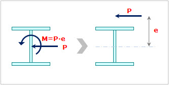
By assigning the eccentricity distance, the user can easily assign an eccentric load.
As shown in the picture below, by inputting the eccentricity distance and load, the program automatically converts them to an equivalent moment. This function is convenient to assign an eccentric beam load, such as wind load.
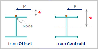
from Offset : Eccentricity from the node with the Section Offset considered
from Centroid : Eccentricity from the centroid
|
Input of the load using the eccentricity |
Eccentricity |
Direction: Input the direction of eccentricity.
Distance: Input the distance of eccentricity.
![]() End: Eccentricity from the
End: Eccentricity from the ![]() node
node
![]() End: Eccentricity from the
End: Eccentricity from the ![]() node
node
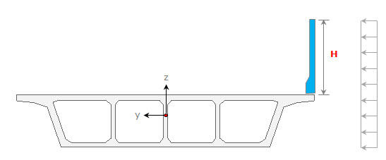
![]() Additional H from Top
Additional H from Top
This option becomes active when the Load Type is Uniform Pressure or Trapezoidal Pressure.
As shown in the figure below, apply the pressure load considering the height of the barrier H that is not the part of the model. Additional H is the distance from the top in the Local y or z (+) direction depending on the load direction.
Additional H for entering the pressure load
 Direction
Set the direction of beam loads. The loading directions are as follows:
Local x: Beam load applied in the element local x-direction
Local y: Beam load applied in the element local y-direction
Local z: Beam load applied in the element local z-direction
Global X: Beam load applied in GCS X-direction
Global Y: Beam load applied in GCS Y-direction
Global Z: Beam load applied in GCS Z-direction
When the loading direction does not correspond to the above 6 directions, enter the force components in each direction with appropriate signs.
Projection
Define if the beam load is to be applied along the entire beam length or if the loading is to be vertically projected on the beam. This command takes effect only when the load type is 'Uniform Loads' or 'Trapezoidal Loads' and the loading direction is 'Global'.
Yes: When a vertically projected beam load is applied to the beam
No: When a beam load is applied along the entire beam length
Value
Define if the loading positions of the beam loads are to be entered in the relative ratio of the beam length.
Relative: Relative ratio of the entire beam length
Absolute: Real beam length
Refer to the figure at the bottom of the Load Type selection field to enter the loading positions for the corresponding loading type and its magnitude.