Soil Pressure
Check soil pressure contours on the beam, plate or solid elements representing subgrade beam, mat foundation or retaining wall.
From the Main Menu select Results > Results > Reactions > Soil Pressure.
![]() Load Cases/Combinations
Load Cases/Combinations
Select a desired load case, load combination or envelope case.
Click ![]() to the right to enter new or modify existing load combinations. (Refer to "Load Cases / Combinations")
to the right to enter new or modify existing load combinations. (Refer to "Load Cases / Combinations")
Step
Specify the step for which the analysis results are to be produced. The Step is defined in geometric nonlinear analysis as Load Step, and additional steps are defined in the construction stages of high-rise buildings or heat of hydration analyses.
![]() Components
Components
Select the desired component among the following:
PX: Soil pressure in the global X-direction
PY: Soil pressure in the global Y-direction
PZ: Soil pressure in the global Z-direction
Local (if defined): Where nodes are assigned Node Local Axis, soil pressure is produced with respect to the local coordinate systems.
Note 1
Pressure contour can be displayed on the beam, plate and solid elements which are assigned Point Spring Support or Distributed Spring Support using the Surface Spring Support function. Note that Point Spring Support entered using the Model > Boundaries > Point Spring Support function is not considered in the calculation of soil pressure.
Note 2
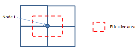
The soil pressure is calculated as the nodal reaction divided by the effective area surrounding the relevant node. The effective area is bounded by the center line of plate/solid element.
![]() Type of Display
Type of Display
Define the type of display as follows :
![]() Batch Output Generation (
Batch Output Generation ( ![]() ,
, ![]() )
)
Given the types of analysis results for Graphic outputs, generate consecutively graphic outputs for selected load cases and combinations. A total number of files equal to the products of the numbers of checked items in the three columns of the dialog box below are created. (Details...)