Search Displacements
Check the displacement of a particular node in numerical values.
From the Main Menu select Results > Results > Deformations > Search Displacements.
|
 Node Picking
![]() Node Number
Node Number
Enter the node number for which the displacement is to be checked, or click the entry field and assign the node with the mouse in the working window.
|
Current Step Disp. |
Produce the displacements pertaining to the selected step of the construction stage if a construction stage analysis has been performed. |
|
Stage/Step Real |
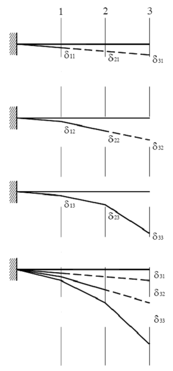
Display the Real Displacements for each construction stage when the construction stage analysis is performed. Note Real displacement is relevant only for construction stage analysis. To illustrate real displacement, a cantilever is constructed in 3 stages as shown below. Node 3 is activated at the stage 3, and the deflection δ33 occurs due to the self weight of the segment 3. But when constructing steel girders or PC girders, the virtual displacements δ31 and δ32 occur at the stage 1 and stage 2 respectively. Real displacement is the summation of virtual displacements, which occur before the corresponding node is even activated and net displacement, which occurs after the node is activated. Real displacement corresponds to the fabrication camber.
|
Note
When the node number is assigned, the following items are displayed in the Message Window :
Node Number
DX: Displacement component in GCS X-direction
DY: Displacement component in GCS Y-direction
DZ: Displacement component in GCS Z-direction
DXYZ: ![]()
RX: Rotation component about GCS X-axis
RY: Rotation component about GCS Y-axis
RZ: Rotation component about GCS Z-axis
RW: Warping component s