Reactions
Trace and graphically display the vehicle loading condition (corresponding moving load case and location) that results in the maximum/minimum reaction of a support. The loading condition is converted into a static loading and produced as a model file of the MCT type. This is an extremely useful feature when we wish to find the loading condition that creates the maximum or minimum reaction.
From the Main Menu select Results > Moving Load > Moving Tracer > Reactions.
 Moving Load Cases
Select a moving load case (vehicle type) that is to be traced and located at a position satisfying the max/min reaction.
![]() Key Node: Enter a support node number, or click the entry field and the desired support in the working window.
Key Node: Enter a support node number, or click the entry field and the desired support in the working window.
Scale Factor: Enter the drawing scale factor for the influence line/surface. This does not affect the influence line/surface values.
|
Type of Display
Assign the type of display.
|
Contour |
Display the contour of the influence line/surface together with the vehicle loading condition.
|
|
|
Ranges: Define the contour ranges.
Number of Colors: Assign the number of colors to be included in the contour (select among 6, 12, 18, 24 colors) Colors: Assign or control the colors of the contour. Color Table: Assign the type of Colors.
Reverse Contour: Check on to reverse the sequence of color variation in the contour. Contour Line: Assign the boundary line color of the contour. Element Edge: Assign the color of element edges while displaying the contour. Contour Options: Specify options for contour representation. Contour Fill Gradient Fill: Display color gradient (shading) in the contour. Draw Contour Line Only Mono line: Display the boundaries of the contour in a mono color. Contour Annotation Spacing: Specify the spacing of the legend or annotation. Coarse Contour (faster) (for large plate or solid model) Extrude
|
|
Legend |
Display various references related to analysis results to the right or left of the working window.
|
|
|
Legend Position: Position of the legend in the display window
|
|
Applied Loads |
Graphically display the vehicle load condition for which the analysis results in the max/min reactions.
|
|
|
Set a detail display condition for the vehicle load case. Load Scale Factor: Enter the drawing scale factor for the load representation Load Values: Option to display the load values |
|
Include Impact Factor |
Reflect the impact factor in the display.
|
|
Include Psi Factor |
This is a display option which does not affect the results but allows users to see the Moving Tracer with and without the Psi factors applied for relevant loads, This option is related to Moving Load Cases with Ignore Psi Factor option checked off and will have no effect on Load Cases with Ignore Factor checked on. |
Maximum Value
Produce the maximum or minimum value calculated from the moving vehicle load analysis.
![]() : Where Influence Line or Influence Surface analysis has been carried out, the moving load case, which produces the maximum or minimum results, is converted into a static loading and produced as an MCT type.
: Where Influence Line or Influence Surface analysis has been carried out, the moving load case, which produces the maximum or minimum results, is converted into a static loading and produced as an MCT type.
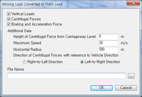
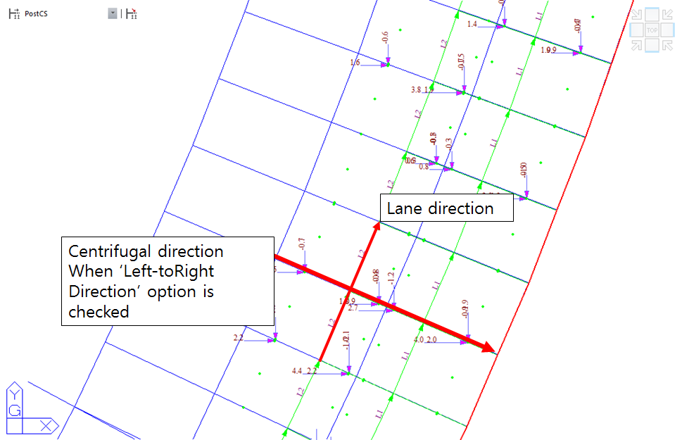
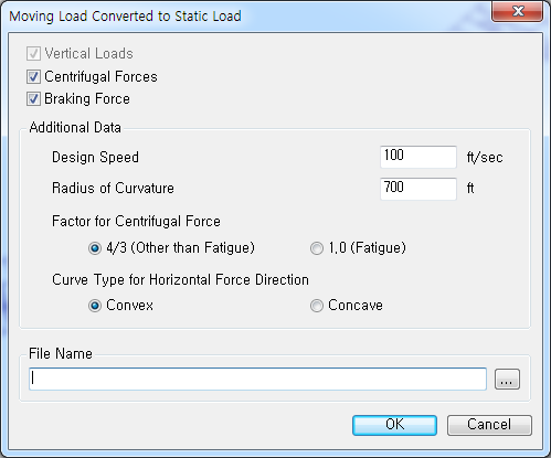
Moving Load Converted to Static Load
![]() When Eurocode or BS is selected for Moving Load Code
When Eurocode or BS is selected for Moving Load Code
![]() When AASHTO LRFD or PennDOT is selected for Moving Load Code
When AASHTO LRFD or PennDOT is selected for Moving Load Code
Detailed Results
Produce Produces a text file detailing the calculation of HA Lane Factors for the current moving load tracer. The report will apply different factors depending on the type of HA vehicle defined and the options chosen by the user as explained below.
HA Lane Factor: BD 37/01 – Lane factors (LF) computed as described in clause BD37/01 Table 14 with adjustment factor (AF) and reduction factor (K) set to 1.
HA Lane Factor: BD 21/01 – Lane factor (LF) applied as given in clause BD21/01 5.24 with adjustment factor (AF) and reduction factor (K) set to 1 as default. If Additional Data option is checked on in the vehicle definition, the values of adjustment factor (AF) and reduction factor will be computed according to clause BD21/01 5.23 and Figure 5.2 to 5.7 respectively.
HA Lane Factor: User-defined – Lane factors (LF) are at default as given in clause BD21/01 5.24 unless modified with adjustment factor (AF) and reduction factor (K) set to 1 as default. If Additional Data option is checked on in the vehicle definition, the values of adjustment factor (AF) and reduction factor (K) will be computed according to clause BD21/01 5.23 and Figure 5.2 to 5.7 respectively.
![]() Revision of Civil 2014
Revision of Civil 2014
Note. Auto-generation of centrifugal forces as per EN1991-2:2003
Centrifugal force due to vehicle load in the horizontally curved bridge can be generated as a static load by selecting "Centrifugal Forces" option.
Following vehicle types are supported:
Road Bridge: Load Model 1 Standard and user-defined vehicle
Railway Bridge: Standard Vehicle – LM71, SW/0, SW/2, Unloaded Train
User Defined Vehicle – LM71, SW/0, SW/2, Unloaded Train
Characteristic value of centrifugal forces are automatically calculated as per EN1991-2:2003, clause 4.4.2 and 6.5.1.
File Name
Enter the file path and name of the MCT file to be output.