Nodal Result of RS Table
Check the inertia forces and accelerations from response spectrum analysis at each node of a structure in a spreadsheet format table.
Table Tool in midas Civil offers a variety of powerful built-in functions. Refer to the following items for detail directions:
Basic directions (Cell motion, selection, size control, etc.)
Data manipulation (Add, delete, modify data, etc.)
Copy/Paste data using clipboard
From the Main Menu select Results > Result Tables > Nodal Result of RS.
Refer to "Nodal Result of RS "
Select a vibration mode for which natural vibration vector will be produced, in the Records Activation Dialog.
In order to display inertia forces and accelerations due to modal combination, select Load Cases only. In order to display inertia forces and accelerations for each mode, select Load Cases and relevant Modes.
Refer to Usage of Table Tool and check the following data:
Results due to modal combination
Load Case: Response Spectrum Load Case
Modal Com.: Modal combination method
Node: Node of a structure
FX, FY, FZ: Nodal inertia force in each direction
MX, MY, MZ: Nodal bending moment in each direction
Mb: Warping moment
DX, DY, DZ: Nodal acceleration in each direction
RX, RY, RZ: Nodal rotational acceleration in each direction
RW: Warping acceleration
Results due to mode selection
Load Case: Response Spectrum Load Case
Mode: Mode selected in the Records Activation Dialog
Node: Node of a structure
FX, FY, FZ: Nodal inertia force in each direction
MX, MY, MZ: Nodal bending moment in each direction
Mb: Warping moment
DX, DY, DZ: Nodal acceleration in each direction
RX, RY, RZ: Nodal rotational acceleration in each direction
RW: Warping acceleration
Note 1
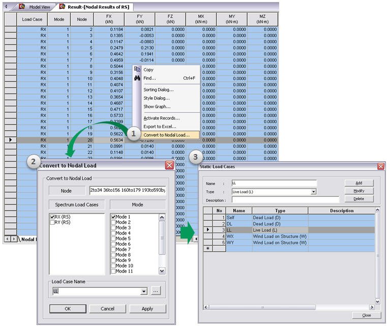
Inertial forces resulting from response spectrum analysis can be converted to nodal loads in the specified load case. The procedure is as follows:
Note 2
When Lumped Mass is selected in Structure Type, inertial force is calculated by Nodal Mass * Base Acceleration.
When Consistent Mass is selected in Structure Type and floor diaphragm is considered, inertial forces of slave nodes will be transferred into that of master node. Therefore inertial forces of slave nodes will be displayed as zero in the table. If there is no generated node in the master node position, inertial forces of all nodes will be displayed as zero.
When Consistent Mass is selected in Structure Type and floor diaphragm is not considered, inertial forces will be calculated using diagonal components in mass matrix.