Member Assignment
A single Member can be assigned when the member is consisted of a number of line elements (beam elements or truss elements).
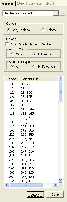
From the Main Menu select Design > Common Parameter > Member Assignment.
From the Menu tab of the Tree Menu select Design > Common Parameter > Member Assignment.
Select the corresponding elements to be assigned as a member, and enter the following
|
|
|
Note 1
When a number of elements are assigned a single Member, the Member number retains the number of the element nearest to the i node. That element then becomes the representative element. All design parameters for the Member must be input corresponding to the most critical element.
Note 2
If the elements to be assigned a Member, retain different material and section properties, or the directions of the node connections are different, a Member can not be assigned.
Note 3
The design parameters, Effective Length Factor (K), Equivalent Moment correction Factor (Cm), Moment Magnifier (B1/δb,B2/δs) and Limiting Slenderness Ratio are taken from the representative element, and Unbraced Length (L,Lb) is taken from each element.