Check Combined Shear and Torsion Strength
Check the combined shear and torsion strength of PSC section in a spreadsheet format table.
Table Tool in midas Civil offers a variety of powerful built-in functions. Refer to Usage of Table Tool for detail directions.
From the Main Menu select PSC > PSC Design Result Table > Check Combined Shear and Torsion Strength
Upon executing the PSC Design Result Table > Check Combined Shear and Torsion Strength, Records Activation Dialog prompts. Click ![]() after selecting the output entities such as elements, part number, Max./Min.
after selecting the output entities such as elements, part number, Max./Min.
Refer to Usage of Table Tool and check the following data:
![]() Revision of Civil 2013
Revision of Civil 2013
When AASTHO LRFD-12 is selected
.jpg)
.jpg)
Elem: Element number
Part: Check location (I-End, J-End) of each element
Max./Min.: Maximum torsion/shear, minimum torsion/shear
LCom. Name: Load combination name.
Type: Displays the set of member forces corresponding to moving load case or settlement load case for which the maximum stresses are produced. If they are not defined then this field is left blank(-)
By default, member forces due to moving load case or settlement load case are not concurrent. In order to consider the concurrent member forces, namely, Fx, Fy, Fz, Mx, My and Mz each having its MAX. and MIN value, the program computes FT, FB, FTL, FBL, FTR, FBR for all these twelve sets.
For example: FT when Fx due to moving load is maximum is 30 N/mm2 and so on..
|
|
FT |
FB |
FTL |
FBL |
FTR |
FBR |
|
Fx- MAX |
30 |
40 |
25 |
35 |
35 |
30 |
|
Fx- MIN |
35 |
30 |
48 |
15 |
25 |
15 |
|
Fy- MAX |
30 |
32 |
37 |
26 |
28 |
21 |
|
Fy- MIN |
25 |
35 |
32 |
28 |
29 |
21 |
|
Fz- MAX |
18 |
15 |
19 |
14 |
15 |
10 |
|
Fz- MIN |
15 |
11 |
12 |
14 |
18 |
10 |
|
Mx- MAX |
1 |
2 |
4 |
1 |
2 |
3 |
|
Mx- MIN |
0.5 |
0.5 |
1 |
1 |
3 |
2 |
|
My- MAX |
18 |
19 |
15 |
22 |
21 |
18 |
|
My- MIN |
14 |
10 |
11 |
15 |
14 |
12 |
|
Mz- MAX |
3 |
9 |
12 |
11 |
8 |
9 |
|
Mz- MIN |
2 |
3 |
8 |
5 |
6 |
7 |
The set that results in maximum stress value FT, FB, FTL, FBL, FTR, FBR is displayed under 'Type' and the maximum stress value is displayed under FMAX. So as per above example, maximum stress value is 48, so it is displayed under FMAX, and it is from Fx-MIN set so under Type, Fx-MIN is displayed. All the values of this set will be displayed.
CHK: Shear and torsion strength check for element (Refer to the equation 5.8.6.5-5 of AASHTO LRFD12)
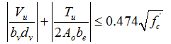
Vu: Factored shear force at section
Mu: Factored moment at section
Tu: Factored torsional moment at section
Vn: Nominal shear resistance at section
▪For non-segmental bridges, (refer to the equation 5.8.3.3-1 and 2 of AASHTO LRFD12)
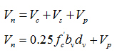
▪For segmental bridges, (refer to the equation 5.8.6.5-1 and 2 of AASHTO LRFD12)

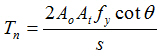
Tn: Nominal torsional resistance at section
▪For segmental bridges, (refer to the equation 5.8.6.4-2 of AASHTO LRFD12)
![]()
▪For non-segmental bridges, (refer to the equation 5.8.3.6.2-1 of AASHTO LRFD12)
Phi: Resistance factor for shear, Phi = 0.9
Phi_t: Resistance factor for torsion, Phi_t = 0.9
Vc: Nominal shear resistance provided by tensile stresses in concrete.
▪For non-segmental bridges, (refer to the equation 5.8.3.3-3 of AASHTO LRFD12)
![]()
▪For segmental bridges, (refer to the equation 5.8.6.5-3 of AASHTO LRFD12)
![]()
Vs: Shear resistance provided by transverse (shear) reinforcement.
▪For non-segmental bridges, (refer to the equation 5.8.3.3-4 of AASHTO LRFD12)
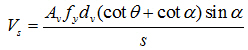
▪For segmental bridges, (refer to the equation 5.8.6.5-4 of AASHTO LRFD12)
![]()
Vp: Component in the direction of applied shear of the effective prestressing force, positive if resisting shear. In midas Civil, shear resistance due to prestressing force, Vp, includes primary prestress force. The secondary effects from prestressing shall be included in the design shear force obtained from the load combinations.
PhiVn: Factored shear resistance
Phi_tTn: Factored torsional resistance
de: Effective depth from extreme compression fibre to the centroid of the tensile force in the tensile reinforcement.
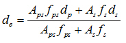
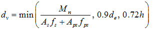
dv: Effective shear depth. Effective web width (bv) is taken as web thickness. For PSC multi-cell girder, web thickness can be automatically taken as a summation of thickness for all webs. Also this value can be entered by the user directly in Section properties > PSC tab.
ex: Longitudinal strain in the web of the member.
theta: Angle of inclination of diagonal compressive stresses. (Refer to the equation 5.8.3.4.2-3 of AASHTO LRFD12)
![]()
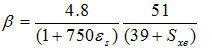
beta: Factor relating effect of longitudinal strain on the shear capacity of concrete, as indicated by the ability of diagonally cracked concrete to transmit tension. (refer to the clause 5.8.3.4.2 of AASHTO LRFD12)
▪For the sections containing at least the minimum amount of transverse reinforcement :
![]()
▪When sections do not contain at least the minimum amount of shear reinforcement:
Avs: Area of Transverse reinforcement within distance s. It is applied as the value of "Fitch" entered in Torsional Reinforcement field of Section Manager.
Ast: Total area of longitudinal mild steel reinforcement. It is applied as the value of "Awt" entered in Torsional Reinforcement field of Section Manager.
Al: Area of longitudinal torsion reinforcement in the exterior web of the box girder. It is applied as the value of "Alt" entered in Torsional Reinforcement field of Section Manager.
bv: Width of web adjusted for the presence of ducts.
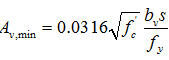
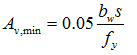
Avs_min: Minimum area of transverse reinforcement within distance s required.
▪For non-segmental bridges, (refer to the equation 5.8.2.5-1 of AASHTO LRFD12)
▪For segmental bridges, (refer to the equation 5.8.2.5-2 of AASHTO LRFD12)
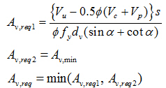
Avs_req: Area of transverse reinforcement required within distance s.
▪ For Vu < 0.5Φ(Vc+Vp)
Skip the transverse reinforcement checks.
▪ For Vu ≥ 0.5Φ(Vc+Vp)
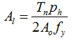
Al_min: Minimum area of longitudinal torsion reinforcement in the exterior web of the box girder required. midas Civil incorporates the following equation to check the longitudinal torsional reinforcement. (Refer to the equation 5.8.3.6.3-2 of AASHTO LRFD 2012.)
bv_min: Minimum width of web adjusted for the presence of ducts required.
At: Total area of transverse torsion reinforcement in the exterior web of cellular members.
At_req: Total area of transverse torsion reinforcement in the exterior web of cellular members required.
When AASTHO LRFD-07 is selected
.jpg)
Elem: Element number
Part: Check location (I-End, J-End) of each element
Max./Min.: Maximum torsion/shear, minimum torsion/shear
LCom. Name: Load combination name.
Type: Displays the set of member forces corresponding to moving load case or settlement load case for which the maximum stresses are produced. If they are not defined then this field is left blank(-)
By default, member forces due to moving load case or settlement load case are not concurrent. In order to consider the concurrent member forces, namely, Fx, Fy, Fz, Mx, My and Mz each having its MAX. and MIN value, the program computes FT, FB, FTL, FBL, FTR, FBR for all these twelve sets.
For example: FT when Fx due to moving load is maximum is 30 N/mm2 and so on..
|
|
FT |
FB |
FTL |
FBL |
FTR |
FBR |
|
Fx- MAX |
30 |
40 |
25 |
35 |
35 |
30 |
|
Fx- MIN |
35 |
30 |
48 |
15 |
25 |
15 |
|
Fy- MAX |
30 |
32 |
37 |
26 |
28 |
21 |
|
Fy- MIN |
25 |
35 |
32 |
28 |
29 |
21 |
|
Fz- MAX |
18 |
15 |
19 |
14 |
15 |
10 |
|
Fz- MIN |
15 |
11 |
12 |
14 |
18 |
10 |
|
Mx- MAX |
1 |
2 |
4 |
1 |
2 |
3 |
|
Mx- MIN |
0.5 |
0.5 |
1 |
1 |
3 |
2 |
|
My- MAX |
18 |
19 |
15 |
22 |
21 |
18 |
|
My- MIN |
14 |
10 |
11 |
15 |
14 |
12 |
|
Mz- MAX |
3 |
9 |
12 |
11 |
8 |
9 |
|
Mz- MIN |
2 |
3 |
8 |
5 |
6 |
7 |
The set that results in maximum stress value FT, FB, FTL, FBL, FTR, FBR is displayed under 'Type' and the maximum stress value is displayed under FMAX. So as per above example, maximum stress value is 48, so it is displayed under FMAX, and it is from Fx-MIN set so under Type, Fx-MIN is displayed. All the values of this set will be displayed.
CHK: Shear strength check for element
Vu: Factored shear force at section
Mu: Factored moment at section
Tu: Factored torsional moment at section
Vn: Nominal shear resistance at section
Tn: Nominal torsional resistance at section
Phi: Resistance factor for shear
Phi_t: Resistance factor for torsion
Vc: Nominal shear resistance provided by tensile stresses in concrete.
Vs: Shear resistance provided by transverse (shear) reinforcement.
Vp: Component in the direction of applied shear of the effective prestressing force, positive if resisting shear.
PhiVn: Factored shear resistance.
Phi_tTn: Factored torsional resistance
.jpg)
de: Effective depth from extreme compression fibre to the centroid of the tensile force in the tensile reinforcement.
dv: Effective shear depth.
ex: Longitudinal strain in the web of the member.
theta: Angle of inclination of diagonal compressive stresses.
beta: Factor relating effect of longitudinal strain on the shear capacity of concrete, as indicated by the ability of diagonally cracked concrete to transmit tension.
Avs: Area of Transverse reinforcement within distance s.
Ast: Total area of longitudinal mild steel reinforcement.
Al: Area of longitudinal torsion reinforcement in the exterior web of the box girder.
bv: Width of web adjusted for the presence of ducts.
Avs_min: Minimum area of transverse reinforcement within distance s required.
Avs_req: Area of transverse reinforcement required within distance s.
Al_min: Minimum area of longitudinal torsion reinforcement in the exterior web of the box girder required.
bv_min: Minimum width of web adjusted for the presence of ducts required.
At: Total area of transverse torsion reinforcement in the exterior web of cellular members.
At_req: Total area of transverse torsion reinforcement in the exterior web of cellular members required.
![]() Revision of Civil 2013
Revision of Civil 2013
When CAS-S6S1-2010 is selected
.jpg)
Elem: Element number
Part: Check location (I-End, J-End) of each element
Max./Min.: Maximum torsion/shear, minimum torsion/shear
LCom. Name: Load combination name.
Type: Displays the set of member forces corresponding to moving load case or settlement load case for which the maximum stresses are produced. If they are not defined then this field is left blank(-)
By default, member forces due to moving load case or settlement load case are not concurrent. In order to consider the concurrent member forces, namely, Fx, Fy, Fz, Mx, My and Mz each having its MAX. and MIN value, the program computes FT, FB, FTL, FBL, FTR, FBR for all these twelve sets.
For example: FT when Fx due to moving load is maximum is 30 N/mm2 and so on..
|
|
FT |
FB |
FTL |
FBL |
FTR |
FBR |
|
Fx- MAX |
30 |
40 |
25 |
35 |
35 |
30 |
|
Fx- MIN |
35 |
30 |
48 |
15 |
25 |
15 |
|
Fy- MAX |
30 |
32 |
37 |
26 |
28 |
21 |
|
Fy- MIN |
25 |
35 |
32 |
28 |
29 |
21 |
|
Fz- MAX |
18 |
15 |
19 |
14 |
15 |
10 |
|
Fz- MIN |
15 |
11 |
12 |
14 |
18 |
10 |
|
Mx- MAX |
1 |
2 |
4 |
1 |
2 |
3 |
|
Mx- MIN |
0.5 |
0.5 |
1 |
1 |
3 |
2 |
|
My- MAX |
18 |
19 |
15 |
22 |
21 |
18 |
|
My- MIN |
14 |
10 |
11 |
15 |
14 |
12 |
|
Mz- MAX |
3 |
9 |
12 |
11 |
8 |
9 |
|
Mz- MIN |
2 |
3 |
8 |
5 |
6 |
7 |
The set that results in maximum stress value FT, FB, FTL, FBL, FTR, FBR is displayed under 'Type' and the maximum stress value is displayed under FMAX. So as per above example, maximum stress value is 48, so it is displayed under FMAX, and it is from Fx-MIN set so under Type, Fx-MIN is displayed. All the values of this set will be displayed.
CHK:Torsion strength check for element
Tf: Factored torsional moment at section
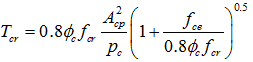
0.2Tcr: Value to check if transverse reinforcement shall be provided. (Refer to the clause 8.9.1.2 of CSA-S6S1-2010.)
If Tf ≤0.25Tcr, transverse reinforcement is ignored.
If Tf ≤0.25Tcr, transverse reinforcement shall be provided.
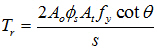
Tr: Factored torsional resistance at section (Refer to the clause 8.9.3.17 of CSA-S6S1-2010.)
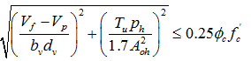
Sig_comb: Stress due to combination of bending moment and shear forces. (Refer to the clause 8.9.3.18 of CSA-S6S1-2010.)
-
For box sections
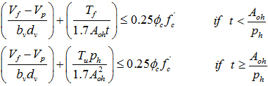
-
For solid sections
0.25PhiF: Combined stress limit (= 0.25Φsf'c)
When EUROCODE2-2:05 is selected
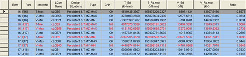
Elem: Element number
Part: Check location (I-End, J-End) of each element
Max./Min.: Maximum torsion/shear, minimum torsion/shear
LCom. Name: Load combination name.
Type: Displays the set of member forces corresponding to moving load case or settlement load case for which the maximum stresses are produced. If it is not defined then this field is left blank(-)
By default, member forces due to moving load case or settlement load case are not concurrent. In order to consider the concurrent member forces, namely, Fx, Fy, Fz, Mx, My and Mz each having its MAX. and MIN value, the program computes FT, FB, FTL, FBL, FTR, FBR for all these twelve sets.
For example: FT when Fx due to moving load is maximum is 30 N/mm2 and so on..
|
|
FT |
FB |
FTL |
FBL |
FTR |
FBR |
|
Fx- MAX |
30 |
40 |
25 |
35 |
35 |
30 |
|
Fx- MIN |
35 |
30 |
48 |
15 |
25 |
15 |
|
Fy- MAX |
30 |
32 |
37 |
26 |
28 |
21 |
|
Fy- MIN |
25 |
35 |
32 |
28 |
29 |
21 |
|
Fz- MAX |
18 |
15 |
19 |
14 |
15 |
10 |
|
Fz- MIN |
15 |
11 |
12 |
14 |
18 |
10 |
|
Mx- MAX |
1 |
2 |
4 |
1 |
2 |
3 |
|
Mx- MIN |
0.5 |
0.5 |
1 |
1 |
3 |
2 |
|
My- MAX |
18 |
19 |
15 |
22 |
21 |
18 |
|
My- MIN |
14 |
10 |
11 |
15 |
14 |
12 |
|
Mz- MAX |
3 |
9 |
12 |
11 |
8 |
9 |
|
Mz- MIN |
2 |
3 |
8 |
5 |
6 |
7 |
The set that results in maximum stress value FT, FB, FTL, FBL, FTR, FBR is displayed under 'Type' and the maximum stress value is displayed under FMAX. So as per above example, maximum stress value is 48, so it is displayed under FMAX, and it is from Fx-MIN set so under Type, Fx-MIN is displayed. All the values of this set will be displayed.
CHK: Shear strength check for element
T_Ed: Maximum torsional moment among Strength/Stress load combinations
T_Rd,max: Design torsional resistance moment.
V_Ed: Maximum shear force among Strength/Stress load combinations
V_Rd,max: The maximum shear resistance of the section.
Ratio: The ratio ![]()