Tendon Profile Generator
Tendon Profile Generator is a tool to define tendon profiles by importing AutoCAD DXF files. The Tendon Profile Generator readily employs the MCT command shell to structurally model and generate the tendon profile.
-
-
-
The Import function permits the use of AutoCAD DXF files.
-
A large number of Tendon Profiles can be defined at one time.
-
Fast and accurate definition of Tendon Profiles.
-
-
From the Main Menu select Tools > Generator > Tendon Profile Generator.
![]() : open a DXF file
: open a DXF file
![]() : select the layer(s) to be displayed in the program
: select the layer(s) to be displayed in the program
![]() : exclude the layer(s) from the Selected Layers list
: exclude the layer(s) from the Selected Layers list
![]() Tendon
Tendon
Name: Enter the tendon profile name.
Property: Enter the tendon property name already defined in the model; that is, the user must define the tendon property in midas Civil first.
Element ID: Enter the element ID to be assigned to the tendon profile.
Curve Type: Specify the type of curvature for tendon placement.
Typical Tendon
This is a function for defining a lumped representative tendon. If this option is checked on and the number of tendons is entered, the generated tendon profile is multiplied by the entered number of tendons when analysis is performed. For simple analysis, such as the schematic design of a bridge, inputting 3-dimensional tendon profiles is time consuming. Therefore, using this function to group or lump tendons, which defines only one representative tendon profile for analysis, the time required for generating the model and performing the analysis can be reduced.
![]() Tendon Selection
Tendon Selection
For x-z plane tendon
-
-
-
-
-
Click
-
Confirm
changed to  , then click on the layer of the desired tendon.
 -
Click
again, and confirm the number of selected tendons with 
-
-
-
-
For x-y plane tendon
-
-
-
-
-
Click
-
Confirm
changed to , then click on the layer of the desired tendon. -
Click
again, and confirm the number of selected tendons with 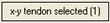
-
-
-
-
Note
How to use ’r;Origin Point’, ’r;x-z plane tendon’ and ’r;x-y plane tendon’ buttons: Click the button first, select a line in the View and click the button again to finish the selection.
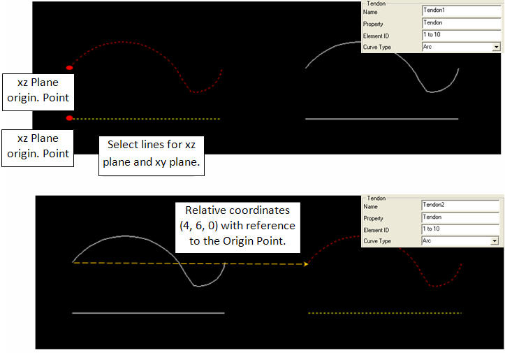
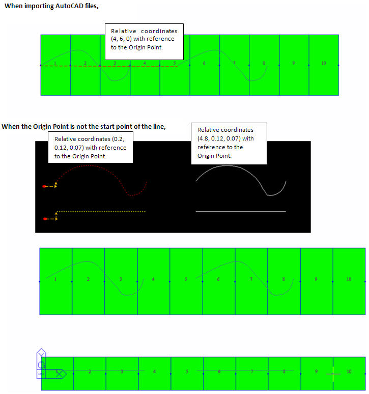
When using the ’r;Origin Point’ button, select a line and the start point of the line becomes the Origin Point. When a point created from CAD is available, select the point as the Origin Point.
When using the ’r;x-z plane tendon’ and ’r;x-y plane tendon’ buttons, select multi-lines if at all.
Tendon Shape
(TCS) for tendon placement is considered as a straight line.
Insertion Point: The origin of the tendon coordinate system (start point of tendon) is identified and inserted into the actual location of the global coordinate system.
Element: Tendon location is relative to the Element Coordinate System.
Start Point: Enter the x, y and z coordinates of the start point of the tendon
Insertion Point (ID): Specify the corresponding element number at which the tendon starts.
End-I of Elem.: I-end of the specified Element is referenced as the insertion point.
End-J of Elem.: J-end of the specified Element is referenced as the insertion point.
x-Axis Direction
In case the Reference Axis is an Element, define the x-axis of the TCS for tendon placement.
I->J of Elem.: The x-axis in the TCS is defined in the direction from the I-end to J-end of the element.
J->I of Elem.: The x-axis in the TCS is defined in the direction from the J-end to I-end of the element.
![]() : Create the tendon profile as per the entered information.
: Create the tendon profile as per the entered information.
![]() : Modify the selected tendon profile.
: Modify the selected tendon profile.
![]() : Delete the selected tendon profile.
: Delete the selected tendon profile.
![]() : Creates a text file with automatically generated commands for the MCT Command Shell. The commands will instruct midas Civil to model the tendon profile(s).
: Creates a text file with automatically generated commands for the MCT Command Shell. The commands will instruct midas Civil to model the tendon profile(s).
![]() : Close the program.
: Close the program.
Note
1. The unit length of the AutoCAD DXF file should be same as the current unit length in midas Civil
2. The tendon shape in the AutoCAD DXF file should be drawn from the left to the right.