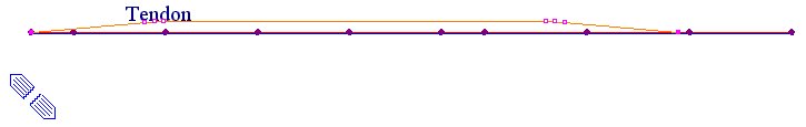
Tendon Profile
Define a tendon profile along the length of elements. Create the tendon profile relative to its own coordinate system, which will then be inserted relative to the elements.
Note
Tendon placement can be simplified by copying, rotating and sloping
tendon profiles.
From the Main Menu select Load > Temp/Prestress > Tendon Profile.
Note
If a Tendon Profile is selected from the Tendon Profile List, the
tendon placement is displayed on the screen.
Click
![]() in the Tendon Profile dialog box to enter new tendon placement.
in the Tendon Profile dialog box to enter new tendon placement.
Click
![]() to change and
to change and ![]() to eliminate a previously defined profile.
to eliminate a previously defined profile.
![]() : Tendon
properties assigned to a number of Tendon Profiles can be changed
at the same time.
: Tendon
properties assigned to a number of Tendon Profiles can be changed
at the same time.
![]() : Tendon
Profile can be exported to DXF as a 2D format (x-z Plane and x-y
Plane).
: Tendon
Profile can be exported to DXF as a 2D format (x-z Plane and x-y
Plane).
Note
If there are a number of Profiles, which are required to have Tendon
Properties changed, this functionality allows us to change them
simultaneously, rather than changing them one by one in each profile.
Click
on the ![]() button to Copy
or Move the inputted Tendon Profile
button to Copy
or Move the inputted Tendon Profile
![]() Mode
Mode
Copy: Copy the selected Tendon Profile
Move: Move the selected Tendon Profile
![]() Translation
Translation
Select one of the following options to Copy/Move the selected Tendon Profile
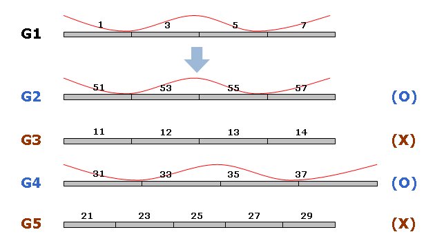
Element Increment: Copy/Move the selected Tendon Profile as per the inputted increment of element number. To Copy/Move the tendon profile defined with this option, at 1, 3, 5, 7 (G1), the following conditions should be satisfied.
• The increment of each corresponding element should be identical
For example, Tendon Profile entered in element 1, 3, 5, 7 (G1) can be Copied/Moved to element 51, 53, 55, 57 (G2) because the increment is identical. On the other hand, the Tendon Profile cannot be Copied/Moved to 11, 12, 13, 14 (G3) because the increment is different for each element.
• The number of elements to Copy/Move should be the same
For example, the Tendon Profile entered in element 1, 3, 5, 7 (G1) can be Copied/Moved to G4 which has the same number of elements. On the other hand, Tendon Profile cannot be Copied/Moved to G5 since the number of elements is different.
As displayed the figure below, the length of each element does not matter while performing the Copy/Move commands.
Element Increment Option
Note
1. Element Increment option can be selected only when the Tendon Profile is defined.
2. Element Increment option is a change of element that is included in Assigned Elements and Insertion Point.
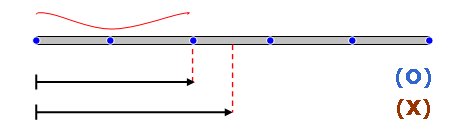
Equal Distance
Enter the absolute distance to Copy/Move the Tendon profile to a particular location. While using this option, the following conditions should be satisfied.
At the distance inputted to Copy/Move the Tendon Profile from the initial Insertion Point of the original element, a node of the element where the Tendon Profile is to be Copied/Moved must exist. This node will define the new Insertion Point. If this node does not exist, then an error message will be displayed.
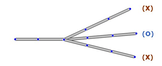
If there is more than one element attached to the initial element, then the Tendon Profile will be assigned to the attached element that is most linear.
If Straight/Curve type Tendon Profile is to be Copied/Moved, then the original length and number of elements should be equal to the length and number of elements at the new location.
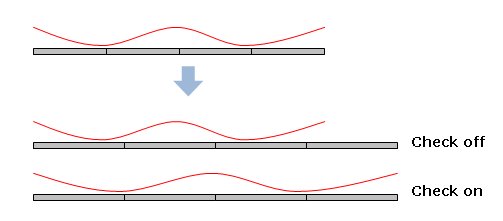
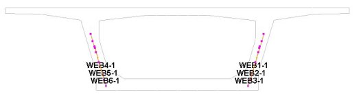
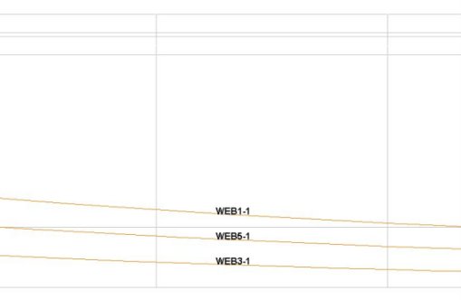
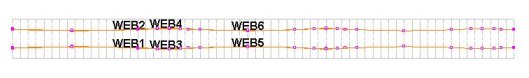
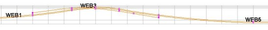
Current Assigned Element: It is used to copy Tendon Profile within an element. This option is useful when generating Web Tendons which exist at different locations of the same element. With this option off, tendons only can be copied if another element exists at the distance specified. However, with this option on, it is possible to copy Tendon Profile irrespective of element existence.
New Assigned Element: Input new Assigned Elements and Insertion Point to Copy/Move a Tendon Profile to those elements.
![]() Auto-Adjustment of
Tendon Length
Auto-Adjustment of
Tendon Length
If a Tendon Profile is Copied/Moved to an element whose total length is different from the total length of the original element, then checking this option will automatically adjust the tendon length based on the ratio of the original element length to the length of the element where the Tendon Profile is copied.
 Move
Move
Move the previously defined tendon layout.
Tendon Name
Note 1
Name assigned within 20 alphanumeric characters
Note
2
Bridge Wizard of midas Civil automatically assigns the following
tendon names:
Group
Define
Tendon Groups. Once Tendon Groups are defined, coordinates, stresses
and prestress losses of tendons can be checked by Tendon Groups.
Click ![]() to the right
to add new, modify or delete previously defined Tendon Groups.
Tendon Groups can be assigned to the tendons having the same tendon
property.
to the right
to add new, modify or delete previously defined Tendon Groups.
Tendon Groups can be assigned to the tendons having the same tendon
property.
Tendon Property
Define
the tendon properties. Click ![]() to the right to add new, modify or delete previously defined tendon
properties.
to the right to add new, modify or delete previously defined tendon
properties.
Assigned Elements
Specify the element numbers to which the tendon will be assigned.
Use the Graphical Selection function of midas Civil to automatically specify the numbers by selecting the elements on the screen.
![]() Input
Type
Input
Type
The dimension of Tendon Profile is specified.
2-D
Tendon Profile is defined in 2-dimensional coordinates.
3-D
Tendon Profile is defined in 3-dimensional coordinates.
Curve
Type
Specify the type of curvature for tendon placement.
Spline
Calculate the minimum polynomial curvature connecting the points
defining the tendon profile and auto-place the tendons
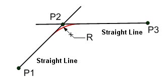
Round
Place the tendons following the circle, which forms tangents to
the straight lines connecting the points defining the tendon profile.
Straight Length of Tendon
Specify the straight portions of the tendon at both ends.
![]() Begin:
at the beginning of the tendon
Begin:
at the beginning of the tendon
![]() End:
at the end of the tendon
End:
at the end of the tendon
Typical Tendon
This is a function for defining a lumped representative tendon. If this option is checked on and the number of tendons is inputted, the generated tendon profile is multiplied by the inputted number of tendons when analysis is performed. For simple analysis, such as the schematic design of a bridge, inputting 3 dimensional tendon profiles is time consuming. Therefore, using the function of lumped representative tendon, which defines only one tendon profile for analysis, the time required for generating the model and performing analysis can be reduced.
After analysis is performed, the tendon results, like tendon loss, elongation etc. are displayed as one tendon.
No. of Tendon: Number of lumped representative tendons
Transfer Length
Enter a Transfer Length. In both pre tensioned and post-tensioned beams, compressive stress due to tendon prestressing forces is not fully distributed to the top and bottom fibers of the member near the end anchorage zones or beam ends over a Transfer Length.
The Transfer Length can be either input by the user or obtained by automatic calculation. For the automatic calculation by formula, two methods are available depending on Tendon Property (Post-tension or Pre-tension).
User Defined Length: Enter a Transfer Length manually.
Begin: Beginning portion of the Transfer Length
End: End portion of the Transfer Length
Auto Calc (0.5x(H+Bf/n): For Post-tensioning, the transfer length is auto-calculated as below.
L=0.5x(H+Bf/n)
where, H: Section depth, Bf: Flange width, n: Number of webs (2 for 1Cell)
Auto Calc (65xStrand Diameter): For Pre-tensioning, the transfer length is auto-calculated as below.
L=65xStrand Diameter
Note
The stress in the prestressing steel is assumed to vary linearly from 0.0 at the point where bonding commences, to the effective stress after losses at the end of the transfer length. Tendon stresses after immediate loss are determined linearly with the transfer length, and then losses due to creep, shrinkage and relaxation will be calculated along the time.
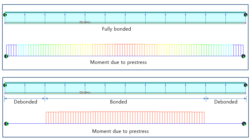
Debonding
Data
Enter the Debonded Length for debonded strand. This option is only available for the pretension type of tendon.
Debonded Length
Begin: Beginning portion of the debonded Length
End: End portion of the debonded Length
Note 1
"Load > Temp./Prestress > Prestress Loads > Tendon Profile > Change Tendon Profile"
Debonded length and transfer length can be modified for the multiple strands at one time.
Note 2
Define the cable profile for the full length of the beam including the debonded part, the program would automatically takes the effect of bonded part according to the value provided in the debonded length at Start & End.
Profile
Place the tendon profile by defining the coordinates of the tendon. The tendon coordinate system (TCS) used here is temporary, and its origin is the starting point of the tendon, which will be related to the elements by the profile insertion point. As many coordinates as required to define the profile may be specified, but at least two (start and end) points are required. The x-axis of TCS is parallel with a Global axis in the length direction, and the z-axis of TCS coincides with the Global Z-axis. See Tendon Shape below for further details.
Reference Axis
Straight: the x-direction (the reference line from which tendon coordinates are defined) of TCS for tendon placement is considered as a straight line.
Curve: the x-direction (the reference line from which tendon coordinates are defined) of TCS for tendon placement is considered as a curved line.
Element: Tendon location is converted into Element Coordinate System and applied.
Note
If Element is selected in Tendon Shape, Tendon Profile moves with
Element's movement.
Note
If Tendon Profile is defined by Element Type, the tendon length
is calculated based on the element length and the elongation may
not be accurate in case of greatly curved tendons. Therefore,
it is recommended to use Straight or Curve Type for defining greatly
curved tendon profiles.
If Spline is selected in Curve Type
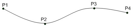
x, y, z: tendon coordinates in TCS
fix: check in the box to specify the tangent to the tendon curvature at the point in question.
Ry: if fix is checked, the angle of the tangent line relative to the x-axis in the TCS x-z Plane
Rz: if fix is checked, the angle of the tangent line relative to the x-axis in the TCS x-y Plane
Note
The tendon profile is created following the geometry specifications
and maintaining the least change of curvatures.
If Round is selected in Curve Type
When Round of Curve Type is selected, the tendon profile is created using straight lines and arcs.
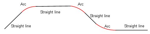
R: Enter the radius of an arc at the corresponding point.
Add
Right: Generate a point to the right of the entered point.
Left: Generate a point to the left of the entered point.
A[deg]: Angle formed from the line connecting the entered point and the additionally created point to the x-axis. The upward direction is (+) and the downward direction is (-) with reference to the x-axis.
h: Distance from the entered point to the additionally created point in the y or z-direction. (Distance should be a positive value.)
r: Radius of an arc at the additionally created point
Note
When 2-D of Input Type and Round of Curve Type are used to create
the Tendon Profile shown in the figure below, it can be simply
created by using the coordinates (x1, y1), (x2, y2) and A1, A2,
h1, h2, r1, r2. When the Tendon is to be placed to the right of
the entered coordinates, select Right in the Add column. When
it is to be placed to the left of the entered coordinates, select
Left in the Add column.
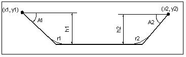
Input Tendon Profile by using 2D Round
BOT: If BOT is checked on two points of a tendon profile, whose vertical distances from the bottom of the section (z distance) are equal, then the vertical distance from the bottom of the section to the tendon remains the same between the two points. However, if the two points where BOT is checked have different vertical distances from the bottom of the section, then the tendon is considered to be a straight line and its coordinates are linearly interpolated at intermediate points.
For the following cases, BOT cannot be checked
If Spline is selected: If the corresponding points are included in a straight line (inputted in Straight Length of Tendon) then BOT cannot be selected.
If Round is selected: If R is inputted on the corresponding point then BOT cannot be selected
Point of Sym.
First: The starting point of the current Tendon is assumed to be the axis of symmetry.
Last: The end point of the current Tendon is assumed to be the axis of symmetry.
![]() : Tendon Profile is created
on the basis of the selected symmetry point (First or Last).
: Tendon Profile is created
on the basis of the selected symmetry point (First or Last).
1. If Straight is selected in Reference Axis
2. If Curve is selected in Reference Axis