Define Contact Parameter


Overview

IMG_C_ICON_DOT.gifUse welded contact elements where element faces meet, but the nodes are not shared, to induce the same behavior.

It can be used as the initial contact conditions between adjacent objects in structural analysis, consolidation analysis or seepage analysis. It is often used when node sharing on very complex geometry needs to be ignored to create an element. This function prevents analysis error and checks the analysis results that are similar to node sharing.

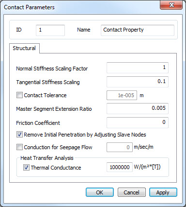
General contact considers the impact and impact friction between two objects in analysis, otherwise two objects are bonded like rigid link each other by welded contact. General contact can be used in nonlinear (static, dynamic) and fully coupled analysis. With Geometric Nonlinearity option, solver will take into account all possible contact area automatically regardless of defined Contact tolerance between two objects. It is also possible to consider Frictional behavior by Friction coefficient between two objects and the penetration at initial stage can be ignored by adjusting slave nodes automatically.


Concept

IMG_C_ICON_DOT.gifContact analysis fundamentally assumes that two objects in a space can be in contact, but cannot penetrate each other (non-penetration condition), and are nonlinear in behavior or condition from a physical point of view. The type of contacts are general contact (considers the impact and impact friction between two objects in analysis), rough contact(does not consider sliding), welded contact (two objects are welded from the start of analysis) and sliding contact (only considers the sliding in the tangent direction). In the example below, general contact and rough contact are assigned depending on the position of two objects at the start of analysis and can be seen as linear. FEA NX supports the welded and general contact feature.


<Concept of General contact and Rough contact>                                            <Concept of Welded contact>


Methodology

Contact element generation (Welded Contact)


The contact can be defined through the Automatic Contact and the Create Manual Contact Pair functions.


Define Contact Parameter


Define the normal and tangential stiffness of contact element. Based on the material properties of adjacent elements, the stiffness will be updated automatically according to the generated strain. Highly recommend to use Default setting for Scaling Factor.


Following is the summary of parameters for the Contact Elements.


Parameter

Reference value (kN, m)

Contact stiffness (Recommend to use default setting)

Normal stiffness scaling

1 (The smaller value, the larger penetration)

Tangential stiffness scaling

0.1 ( Normal stiffness / 10)

Advanced options (parameters)

Contact Tolerance

Auto (Uncheck) : Find contact area within the tolerance

Friction Coefficient (Optional)

0.3 ~ 0.6 (Depending on material types)

Conduction for Seepage Flow

Impermeable (Uncheck) : Possible to allow seepage flow through the contact elements

Thermal Conductance

Property used to describe ability to conduct heat between two bodies in contact.