Advanced Selection Application
![]()
The geometric characteristics and topology can also be implemented in the modeling process in GTS. Therefore, the geometric entities which include special characteristics, such as direction and plane, can be selected.
The following examples are the most frequently
used cases of utilizing the geometric characteristics and topology in
GTS.
To Define Direction or Revolution Axis
It is important to note when executing commands such as Translate, Extrude, Project, Rotate and Revolve, the user must define the direction or revolution axis to complete the operation.
In GTS,
the direction and the revolution axis can be defined using various entities
which have the relevant characteristics.
|
Allowed Entity |
Geometric Characteristic |
Selection Filter |
|
Datum Axis (1) |
The direction of Datum Axis |
Datum Axis |
|
Datum Plane |
The normal direction of Datum Plane
|
Datum Plane |
|
Edge (Straight Line) |
The direction of straight line |
Edge |
|
Edge (Circle or Arc) |
The normal direction of plane defined by circle or arc
|
Edge |
|
Face (Plane Face) |
The normal direction of plane face
|
Face |
|
Face (Revolved Face) |
The central axis of revolved face (cylinder, etc.)
|
Face |
|
2 Point Vector |
The user-defined 2 point vector |
N/A |
|
Normal of Profile (2) |
The normal direction of executing object (planar entity) |
N/A |
| (1) The Datum Axis is set as default in the Selection Filter for defining the direction and the revolution axis. (2) Its use is limited to some special functions such as Extrude and Local Prism. |
||
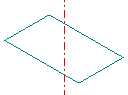

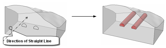
To create tunnels in 3D space, 2D edges are extruded in the direction of
the existing straight line (the same direction also can be applied by
selecting the tunnel section)
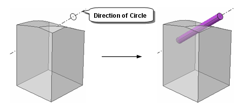
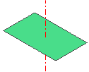
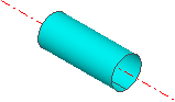
To create a pipe from a circle, the extrusion direction can be defined
by the normal direction of the plane where the circle presents.
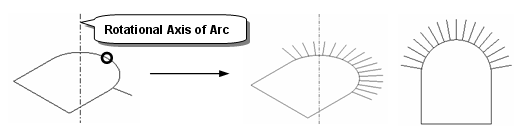
To copy the propeller by rotating around the axis, it is convenient to
select the center arc as revolution axis. The revolved body face can also
be selected.
![]() As shown in the above examples, any direction
and rotational axis can be easily defined using the unique characteristic
of the geometric entities.
As shown in the above examples, any direction
and rotational axis can be easily defined using the unique characteristic
of the geometric entities.
![]() In addition, GTS provides
various snap functions for defining the 2 Point
Vector and the 3 Point Plane, and it highly increases the workability
during complex modeling procedure.
In addition, GTS provides
various snap functions for defining the 2 Point
Vector and the 3 Point Plane, and it highly increases the workability
during complex modeling procedure.
To Select using the Topological Relationship of Geometry Shapes
Due to the concept of topological relationship
in GTS, the selection of Sub-Shapes
can be done by using higher level geometry. In other words, by selecting
a higher level entity, the user can select all of its Sub-Shapes at once.
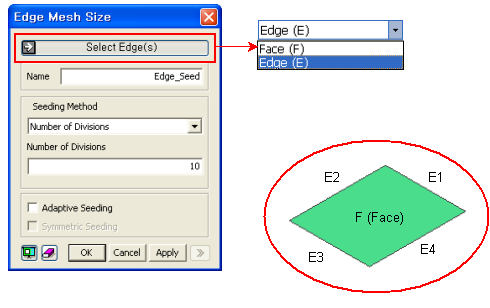
<Selecting Sub-Shapes using Upper Shape>
For example, in the above figure each edge
must be selected separately if the Selection Filter is set to Edge. However,
by setting the Selection Filter to Face, the user can select the four
Sub-Edges at once. Thus, it is recommended that a higher level entity
be used if all of its Sub-Shapes are to be selected.
To Select Nodes and Elements
After setting the Selection Filter to Mesh, the user can select Mesh Sets from the Work Window or the Works Tree. Since nodes and elements are included in a Mesh Set, all of them will be selected together at the same time.
If mesh is generated on Geometry, its nodes
and elements can be selected by the Geometry unit such as Face or Edge.
In order to select any item by Geometry, that item must be visible on
the screen.
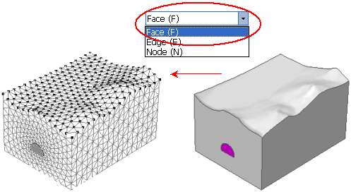
Selecting Nodes which are belong to Terrain Surface
![]() In order to select any items by Geometry,
that item must be visible on the screen.
In order to select any items by Geometry,
that item must be visible on the screen.
Other Useful Selection Tools
In order to provide maximum workability to apply the load and boundary conditions, GTS offers additional selecting tools which are customized specially for the load and boundary conditions.
The most frequently used tools among them
are the Free Face selection in 3D mesh and the Free Edge selection in
2D mesh.
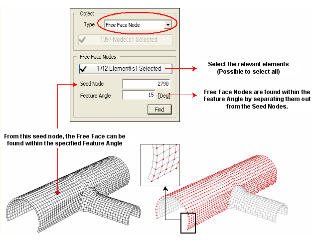
Example of selecting Upper (Lining) for 3D Mesh
Free Face Node selection