Property Window
![]()
The Property Window is used to provide a set of information about the object that is selected from the Work Window or the Works Tree. Depending on the actual working mode Pre-Process, Post-Process, Analysis the Property Window functions differently.
Property Window can be positioned anywhere within the program. Hiding/Showing of the Window can be controlled through <Window> in the Main Menu.
![]() In order to be displayed in the Property Window,
the user must select a single object, and each type of selected object
has a different format of the Property Window. Therefore, it is recommended
to recognize how it differs by each selection.
In order to be displayed in the Property Window,
the user must select a single object, and each type of selected object
has a different format of the Property Window. Therefore, it is recommended
to recognize how it differs by each selection.
In the Pre-processing Mode, general information about the selected object is displayed. Simple modification of basic properties, such as name and color, can be done in the Property Window.
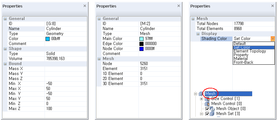
Geometry Entity
Geometric Entity displays common information such as internal ID, name, type and color. Depending on the type of selected entity (Curve, Surface or Solid), it provides geometric characteristics such as length, area and volume.
Mesh Set
Mesh Set displays common information such
as internal ID, name, type and color, as well as the number of nodes or
elements that are included in the selected Mesh Set.
![]() In the Property Window, the user can directly
change color and name of selected Geometry or Mesh Set.
In the Property Window, the user can directly
change color and name of selected Geometry or Mesh Set.
Mesh
By selecting <Mesh> in the Works Tree, the Property Window will show mesh information of the project, such as the total number of nodes and elements in the project and mesh shading options.
![]() Please refer to the section on Graphic Display
Mesh
Please refer to the section on Graphic Display
Mesh
Property and Material
It displays common information about the selected Property or Material, such as name, type, and color.
Load and Boundary Conditions
It displays common information about the
selected Load or Boundary Condition, such as type, number of applied objects
(nodes, elements, faces, etc.).