Geometry Topology Definition
![]()
GTS allows its users to create highly complex geometric data for an accurate FE analysis model with any dimensions or shapes, by providing advanced geometric functions.
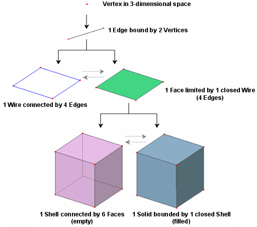
A geometry model is fundamentally formed by the interlocking relationship
of various geometric entities. The geometric entities in GTS
are listed in the following table.
|
Compound |
Group of independent entities | |
|
Shape |
General term used for defining an independent entity | |
|
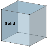
Solid |
Part of 3-D space bound by a shell | |
|
Surface |
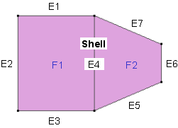
Shell |
A group of Faces connected by boundary edges |
|
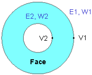
Face |
Part of a plane or a surface bounded by a
closed wire | |
|
Curve |
Wire |
A sequence of Edges connected by their Vertices |
|
Edge |
A shape corresponding to a curve and bound
by a Vertex at each extremity | |
|
Vertex |
A zero-dimensional shape corresponding to
a point in Geometry | |
![]() Selection Filter enables selection of desired shapes
by its geometrical type. (refer
to Selection Filter)
Selection Filter enables selection of desired shapes
by its geometrical type. (refer
to Selection Filter)
<Geometry Shape Definition and Topology>
The boundary of a Face consists of one Wire and the boundary of a Solid consists of one Shell.
The user may interchange freely between closed Wire and Face or between closed Shell and Solid because they are subject to share the same Sub-Shapes.
Extruding an Edge creates a Face. Extruding a Wire creates a Shell. This Shell shares the same Sub-Shapes with a group of Faces which is generated by the extrusion of the original Sub-Edges of the Wire.
Extrude, Revolve, Loft, Sweep and Turning on Solid options will transform the shape into a Solid.
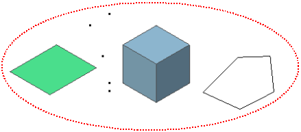
<Compound>
Compound is generally used to sort shapes easily (Ex: grouping hundreds of Curves imported from AutoCAD .dxf file into a single Compound). The above example is a Compound of 8 Shapes (5 Vertices, 1 Wire, 1 Face and 1 Solid). Once the shapes are grouped into a Compound, they do not exist as independent Shapes any longer. The Compound becomes the highest level independent shape. However, since their geometrical type remains unchanged, they still can be utilized in general modeling operations.
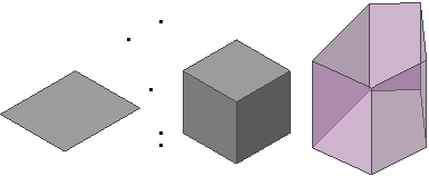
<A Shell extruded from a Wire in the above Compound>
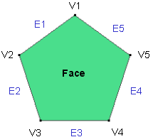
The following examples will help to more comprehensively understand the topology.
|
|
| ||||||||||
|
|
| ||||||||||
|
|
| ||||||||||||
|
|
| ||||||||||||||
GTS provides both the Top-down
Modeling and Bottom-up Modeling methods.
Top-down Modeling Method
In this method, the user creates the highest
level Shape, and its Sub-Shapes are formed automatically. The user does
not need a lot of effort to model each Sub-Shape. This method is often
exercised for a simply shaped model or for a preliminary design process.
![]() <Ex> If a cube is created with the primitive box feature
of GTS, all Sub-Shapes of this solid, such as Faces, Wires and Edges are
automatically generated.
<Ex> If a cube is created with the primitive box feature
of GTS, all Sub-Shapes of this solid, such as Faces, Wires and Edges are
automatically generated.
Bottom-up Modeling Method
The user will start to model from the lowest
level entities first. With these independently generated Sub-Shapes, the
final shape is assembled together. The operation may take more time than
the Top-down Modeling Method. However, by
using this method, the user can generate a very complex shape which cannot
be accomplished by the other method. In most of the geometry modeling
practices, the Bottom-up Modeling Method is used.
![]() <Ex> A surface model of terrain is extremely difficult
to model directly at once. Therefore, Vertices and Edges, which express
the Face, will be created first, and the Face will be generated by using
those Vertices and Edges.
<Ex> A surface model of terrain is extremely difficult
to model directly at once. Therefore, Vertices and Edges, which express
the Face, will be created first, and the Face will be generated by using
those Vertices and Edges.
![]() It is not always necessary
to follow each step from the lowest level shape to the complete model
in the Bottom-up Modeling Method. Some procedures can be eliminated if
necessary.
It is not always necessary
to follow each step from the lowest level shape to the complete model
in the Bottom-up Modeling Method. Some procedures can be eliminated if
necessary.
![]() GTS
provides both Top-down Modeling and Bottom-up Modeling methods. Therefore,
the user can choose either method, or a combination of both, depending
on beneficial characteristics of the particular model.
GTS
provides both Top-down Modeling and Bottom-up Modeling methods. Therefore,
the user can choose either method, or a combination of both, depending
on beneficial characteristics of the particular model.
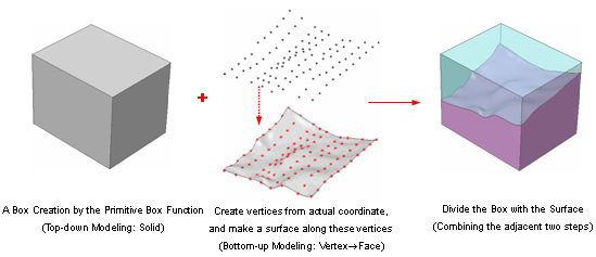
<Example of Combining the Two Modeling Methods>