Post: Clipping Plane
![]()
Function
Clipping planes allows users to view sections
by cutting the working model using clipping planes.
Call
Property Window > Clipping Plane
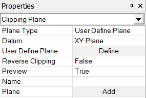
<Clipping Plane Menu in Property Window>
Plane Type
Specify a type of plane to be used in Clipping Plane.
Datum
Contour
Specify Clipping Plane using a pre-defined Datum Plane which is selected
in 'Datum.'
User Define Plane
Define
a Clipping Plane directly by entering values in the Define Plane dialog
box or by using the mouse in the Work Window.
Reverse Clipping
Reverse
the part to be contoured.
Preview
True
It displays
the defined Clipping Plane when user click the Apply button in the Property
Window or the Plot button in the Define Plane dialog box.
False
It displays
only registered Clipping Planes by clicking the Add button.
Name
Enter
the name of defined Clipping Plane.
Plane
Shows the list of registered Clipping Planes by clicking the Add button.
Notes
<How to utilize User Define
Plane>
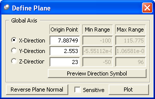
<Define Plane dialog box>
How to use in the Work Window
To move parallel to the Plane
1. Click
the left button of the mouse at any location in the grey plane which appears
in the Work Window..
2. Drag the mouse pointer left to right, and the Clipping Plane moves parallel
to the plane (same as the direction of arrow).
To rotate about the rotating center
1. Click
at the head or tail of the arrow which appears in the Work Window.
2. Drag the mouse pointer left to right, and the Clipping Plane rotates
about the rotating center (the grey dot in the plane).
To move the rotating center
1. Click
the wheel (middle) button of the mouse at the any location in the grey
plane.
2. Drag the mouse pointer left to right, and the rotating center changes
as well as the Clipping Plane (parallel to the plane).
To resize the grey plane
1. Click
the right button of the mouse at the any location in the grey plane.
2. Drag the mouse pointer left to right, and the size of the grey plane
changes.
Once
the slice plane is located as desired, click on the plot button in the
Define Plane dialog box or the apply button in the Property Window
How to input values in the Define Plane dialog box
Global Axis
Define
a Clipping Plane by entering value for the Global Axis.
X Direction
Enter a value in the Global X-direction to create a plane which is perpendicular to the axis.
Y Direction
Enter a value in the Global Y-direction to create a plane which is perpendicular to the axis.
Z Direction
Enter a value in the Global Z-direction to create a plane which is perpendicular to the axis.
Preview Direction Symbol
Preview
the defined plane on the screen.
Reverse Plane Normal
Reveres
the direction of plane normal. Although it does not a significant meaning
in the Slice Plane definition, the contouring part of the Slice Plane
is determined the normal direction.
Sensitive
It immediately updates the figure on the screen as we define the plane.