Generator Feature: Loft Shape
![]()
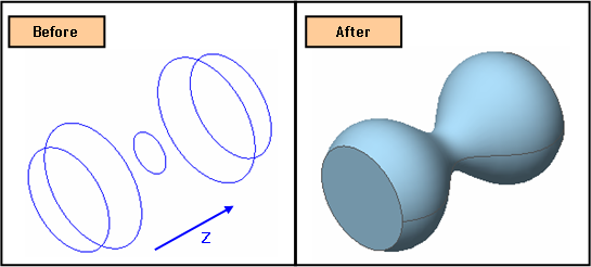
Function
Loft
creates a Shell by connecting section profiles
(Wire, Edge).
Call
Geometry > Generator Feature > Loft
Select Section Profiles
Select
section profiles to which a Loft operation will be applied. Here, the
outcome shape is dependent on Ordering Method.
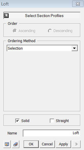
Ordering Method
Selection
The lofted shape is created by connecting Section Profiles in the order of selection. Therefore, it is necessary to select them one by one.
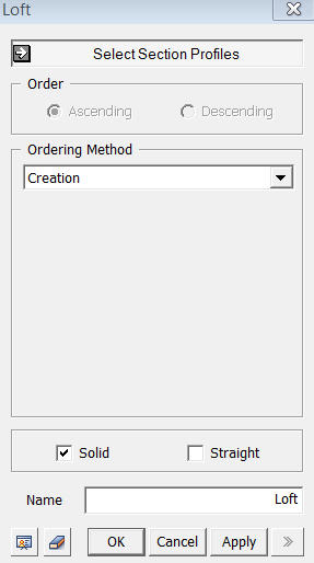
Creation
The lofted shape is created by connecting Section Profiles in the order of creation. User can select multiple profiles at once.
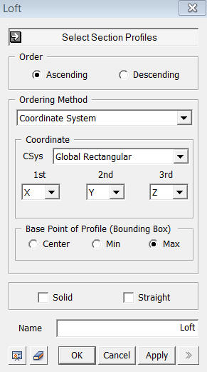
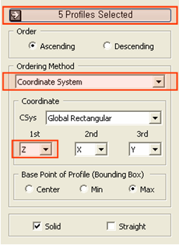
Coordinate System
The
lofted shape is created by connecting Section Profiles according to
Coordinate
Select the coordinate system and specify the priority order of axes. In
order to determine the position of profiles, user needs to specify Base
Point of Profile. The Base Point is based on profile's Bounding Box.
<Loft>
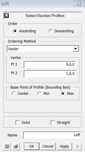
Vector
The
lofted shape is created by connecting Section Profiles in the direction
defined by 2 points vector. The coordinates of 2 points can be specified
by manual input or using Snap. Base Point of Profile is also similarly
applicable in Vector Ordering Method.
Name
Enter the name of a Shape to be created.
Solid
This
option is used to create a Solid using a closed Wire or Edge.
Straight
This option creates a shell by joining each selected section profile in straight lines rather than curved lines.
Notes
To make solid, the first and last profiles must be closed and planar. In order do make Solid, user must create top and bottom faces separately and sew each faces together into a Solid using Main Menu>Surface>Sew.
Often,
result shape may become twisted because curve directions of each profile
is reversed.