Mesh Common Functions
![]()
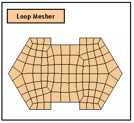
Construct meshes using the Loop Mesh generating
algorithm.
Quadrilateral
Generate Quadrilateral 2D meshes.
Triangle
Generate Triangular 2D meshes.
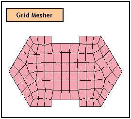
Construct meshes using the Grid Mesh generating
algorithm.
Quad
+
Generate 2D meshes using both Quadrilaterals and Triangles.
Triangle
Generate Triangle 2D meshes.
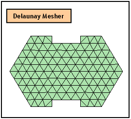
Delaunay
Mesher
Construct meshes using the
Quadrilateral
Generate 2D meshes using both Quadrilaterals and Triangles.
Quad
+
Generate 2D meshes using both Quadrilaterals and Triangles.
Triangle
Generate Triangle 2D meshes.
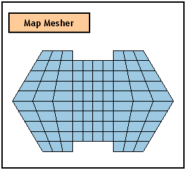
Map
Mesher
Construct meshes using the Mapped Mesh generating algorithm.
Quadrilateral
Generate
Quadrilateral 2D meshes.
Triangle
Generate
Triangle 2D meshes.
Backup
Select
a Backup
Select Corner Vertices
The
Mapped Mesh generation algorithm maps a selected shape into squares and
creates a square mesh and then maps the mesh created from the original
shape.
Refinement Factor
The size of elements within
the selected shapes is determined.
![]()
Assign
an Attribute ID, which will be assigned to the generated mesh. It can
be specified using previously generated Attribute or creating a new by
clicking ![]() button. If user would like to apply the same Attribute
with previously generated Mesh, click
button. If user would like to apply the same Attribute
with previously generated Mesh, click ![]() button and select a Mesh Set which has the desired Attribute
from the Work Window.
button and select a Mesh Set which has the desired Attribute
from the Work Window.
Add to
Register
the generated mesh in a Mesh Set. It can be selected from the Mesh Set
list which is located on the right of 'Add to' or from the Work Window
by using ![]() button.
button.
If
'Mesh Set' is selected from the list, a new Mesh Set is registered containing
the generated mesh. The name of a new Mesh Set will be Auto-Mesh(3D) by
default.
As Sub-Set
The new generated mesh becomes registered in a sub Mesh Set of the selected Mesh Set. This option activates when a Mesh Set is selected from the list.
When generating mesh sets
for selected solids, this option will merge nodes at free edges.
Creates a node in the middle
of each element edge. Consequently, generated element becomes high ordered.
Deletes the Source 2D meshes
after generating mesh.
Hides the object edges
after generating meshes.
Meshes
only the unmeshed faces among the selected faces.
Skips any solid geometry that is unable to generate a solid mesh.
Attempts to generate a linear Mapped-Mesh.
Refer to Generate Mid-side nodes on map mesh for details.
Matches the connectivity of nodes at the contact face between two solids.
Post Remesh can be set before automeshing.
Improves
the quality of quadrilateral finite element meshes.
Hides the object faces after generating meshes.
Hides the object solids after generating meshes.
When creating connecting elements, Beta Angle, the coordinates of Reference Point, or Reference Vector are specified to define the orientation of sections.
Beta Angle
Enter
the Beta Angle (β) to identify the orientation of each cross-section.
The Beta Angle relates the
Ref
If
the coordinates of the Reference Node are entered, it internally computes
the angle of the point and enters the angle as a Beta Angle automatically.
Ref
If
the coordinates of the Reference Vector are entered, ![]() button enables to select a vector (Datum
Axis, Datum Plane, Face, Edge) from the Work Window.
button enables to select a vector (Datum
Axis, Datum Plane, Face, Edge) from the Work Window.
Meshed
tetra elements that have all nodes lying along the outer boundary edges
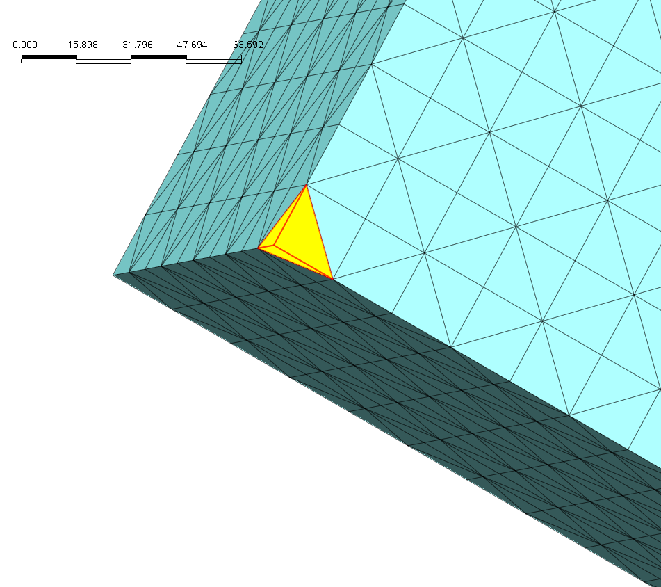
The
element highlighted in yellow represents a clamped element. since all
3 nodes are on the boundary edges.