Property - Pile
![]()
Function
Change the nodal coordinate system of selected nodes.
Call
Model > Element > Create Pile
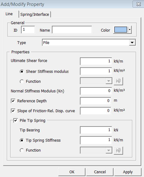
General
ID
Property
ID number
Name
Property
Name.
Color
Select
the color of Property.
Properties
Ultimate Shear Force
Limit Shear Resistance
Shear Stiffness Modulus
Inside Lateral Boundary Stiffness
Function
Select a function to define shear stiffness of boundary
If
the function is not defined, click ![]() button. (Refer to Model
> Function...)
button. (Refer to Model
> Function...)
Normal Stiffness Modulus (Kn)
Slope of normal stress normal displacement curve or outside vertical boundary stiffness
Reference Depth
Reference depth of material model of Pile element
Slope of Friction-Rel. Disp. curve
Changing rate of relative displacement-friction curve at the allocated point.
Pile Tip Spring:
Tip Bearing Capacity: Maximum bearing force allowed at the pile tip
Tip Spring Stiffness: An initial elastic stiffness used before pile tip failure. If this option is chosen, the pile tip will behave elastically until reaching the specified bearing capacity where it then behaves in a perfectly plastic way. Note that it is advised to specify an elastic stiffness at the tip which is large enough to produce negligible displacement but smaller than the shear stiffness modulus of the shaft over the pile length in order to increase the robustness of the numerical analysis.
Function:
Note: Pile tips will be created at the extremity of maximum X coordinate according to orientation of local element coordinate axis of pile elements. Therefore, users are advised to check the local coordinate axes of pile elements before performing the analysis.