Tunnel Modeling Wizard: Step 4 : Mesh
![]()
Function
Tunnel
Modeling Wizard (TMW) automates almost all the time-consuming operations
of three dimensional modelling and produces output data reports for swift
interpretation of analysis results.
The general modelling procedure for TMW consists of 5 major steps: (a) configuration of a tunnel cross section and excavation type; (b) specification of shotcrete and rock bolts; (c) definition of excavation and construction stages; (d) configuration of mesh data with terrain and strata; and (e) preparation of reports with output data.
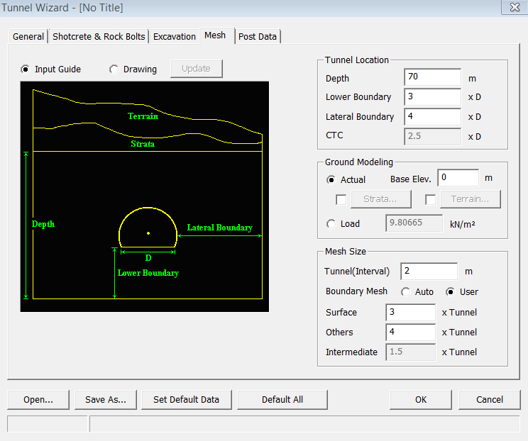
The Mesh tab of TMW is used to define the location of tunnel(s), the boundaries of subsurface and pillar width in case of two tunnels. If the location of the tunnel is relatively close to the ground, it is crucial to consider the impact of the ground weight difference in the analysis. Consequently, TMW provides advanced surface modelling tools, which can generate an analysis model with actual terrain and strata. Having defined all the geometric parameters, information for mesh generation should be provided.
Call
<Tunnel Wizard-Mesh>
Input Guide
It
displays a figure which shows the necessary parameters for mesh generation.
Drawing
It
displays a figure which shows the defined scaled model. Click ![]() button to update
the figure.
button to update
the figure.
Tunnel Location
Define
the tunnel location.
Depth
Enter
the depth of the model.
Lower Boundary
Enter
the distance from the bottom of the tunnel to the lower boundary of the
model.
Lateral Boundary
Enter
the distance from the side of tunnel to the side boundary of the model.
CTC
Enter
the center-to-center distance between the two tunnels in terms of the
ratio of the bottom width of the tunnel.
Ground Modeling
Specify
options for the layers above ground.
Actual
Model
the layers above ground as an actual meshed model .
Base Elev.
Specify
the Z-coordinate of the lower boundary tunnel which becomes the reference
for the strata and terrain elevation.
Strata
If a
model has a stratum, check and click the ![]() button to define the stratum data by entering its
boundary information.
button to define the stratum data by entering its
boundary information.
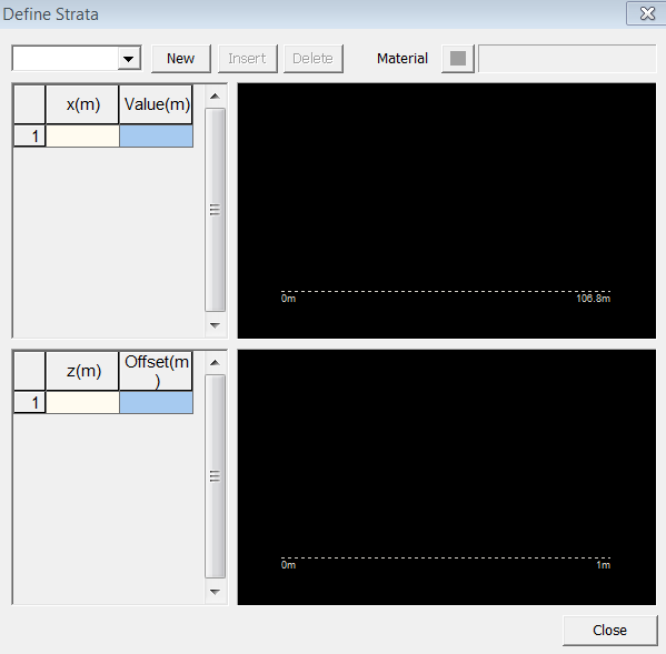
<Tunnel Wizard-Define Strata>
![]()
Click to create a new stratum profile.
![]()
Click to insert a stratum profile.
![]()
Click
to delete a stratum profile.
Material
Click
![]() button to define the material properties of the mesh between the selected
stratum and the lower stratum. If a lower stratum does not exist, it is
applied to the mesh between the selected stratum and the general mesh.
button to define the material properties of the mesh between the selected
stratum and the lower stratum. If a lower stratum does not exist, it is
applied to the mesh between the selected stratum and the general mesh.
x
Define the stratum shape along the Global X-direction. Enter x coordinates where the elevations are specified. The origin is located at the left bottom corner when the model is viewed from the front.
Value
Enter the elevation for entered X coordinates. The preview of the shape appears in the figure on the right.
z
Define the stratum shape along the Global Y-direction (WCS Z-direction). Enter z coordinates where the elevations are specified. The origin is located at the left bottom corner when the model is viewed from the front.
Offset
Enter
the elevation for entered Y coordinates. The preview of the shape appears
in the figure on the right.
Terrain
Define
a terrain surface for the model. The surface is created in the same way
as a Grid Face, by defining elevation at the virtual grid coordinates.

<Tunnel Wizard-Define Terrain>
Size
Enter
the number of virtual grid lines (N x M). Click ![]() button to update the size of table.
button to update the size of table.
Material
Click
![]() button to define the material properties of the mesh between the terrain
surface and the lower stratum. If a lower stratum does not exist, it is
applied to the mesh between the selected stratum and the general mesh.
button to define the material properties of the mesh between the terrain
surface and the lower stratum. If a lower stratum does not exist, it is
applied to the mesh between the selected stratum and the general mesh.
![]()
Import a text file which contains the grid elevation data.
The elevation data table is also compatible with MS-Excel.
![]()
Save
the current input elevation data as a text file.
Load
It does
not model the upper layers of the ground. Instead, the relevant load pressure
will be applied directly.
Mesh Size
Specify general mesh sizes.
Tunnel (Interval)
Enter the mesh size for the tunnel.
Boundary Mesh
Specify
the mesh size for boundary surfaces. It is entered as the ratio to the
tunnel mesh size.
Auto
It will be set by the program.
User
Directly
input the user-defined mesh size.
Surface
Enter the mesh size for upper surfaces (terrain and strata).
Others
Enter the mesh size for any area other than terrain and strata.
Intermediate
Enter
the mesh size for the intermediate wall for the CD Cut excavation method.
![]()
Open
a Tunnel Wizard Save file (*.wzd).
![]()
Save
the current data to a Tunnel Wizard Save file (*.wzd).
![]()
Make
the current data as the default of TMW.
![]()
Reset all data to the default data.
Notes
Please refer to Basic Tutorial 2 for more details on the functions of TMW.