
Function
Stress-strain relationships between reinforcing steel and concrete are defined to carry out inelastic time history analysis using Fiber Elements. Each model is unique based on the proponents and specifications.
Call
Select Geometry > Properties > Fiber Material Properties in the Menu tab of the Tree Menu.
Entry
The properties of fiber materials are defined.
-Add(b).jpg) : Enter or
add a new fiber material property.
: Enter or
add a new fiber material property.
-Modify(b).jpg) : Modify or
check a fiber material property previously defined.
: Modify or
check a fiber material property previously defined.
-delete(b).jpg) : Delete a
fiber material property previously defined.
: Delete a
fiber material property previously defined.
Name: Name of a fiber element model to be defined
Material Type: Steel or concrete for which a hysteresis model will be defined
Hysteresis Model: Select a hysteresis model to define a fiber element out of 4 reinforcing steel models and 5 concrete models.
Skeleton Curve: Specify the property values defining the hysteretic behavior of the fiber material following the diagram.
 Concrete
This Kent and Park (1973) concrete model, which was modified by Scott, et al. (1982), can consider the Confinement Effect due to reinforcing and is rated highly because of its clear formation and accurate analysis.
.bmp)
Inelastic Material Model
|
|
Concrete compressive cylinder strength |
|
|
Factor, which accounts for the strength increase due to confinement |
|
|
|
|
|
Strain at compressive Crushing |
|
|
Strain at maximum compressive strength |
|
|
|
|
|
Strain softening slope - coefficient representing the stiffness in the concrete softening zone after compression yielding |
|
|
Sh: Center to center spacing of stirrups or hoop sets |
Note can be obtained by the proposed equation of Scott et al,
or another value may be used at user's discretion.
can be obtained by the proposed equation of Scott et al,
or another value may be used at user's discretion.
In this model, the concrete tensile strength is ignored since it has little effect on the entire member.
Hysteresis characteristics of this model are as follows:
a. When a member is unloaded under compression,
its behavior is represented by the line connecting  and
and  ; where is
the strain at the beginning of unloading and is
a certain point on the strain axis. As the compression increases, the
slope of this line becomes flatter. The relationship is defined as:
; where is
the strain at the beginning of unloading and is
a certain point on the strain axis. As the compression increases, the
slope of this line becomes flatter. The relationship is defined as:
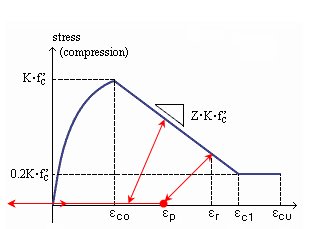
b. Tensile strength is ignored in this model. Therefore, under Complete Unloading or Open Crack, the stress becomes zero (as shown in the above figure).
c. When reloaded, the stress values before
attaining shall
be taken as zero Once the compressive strain exceeds ,
reloading is applied along the line where the unloading occurred. In reality,
Unloading and Reloading cannot be applied linearly, since it is actually
a nonlinear application. However since there is not much difference between
linear and nonlinear behavior, the results will be accurate enough even
if linear Unloading and Reloading is assumed
 Japan Concrete Standard Specification Model
This model is presented in Seismic Performance Comparison Investigation, P23 of Japanese Concrete Standard Specification. Softening zone after the maximum stress, residual plastic deformation and stiffness reduction effect under the condition of reloading after unloading are reflected.
.bmp)
 : Compressive strength of
concrete cylinder
: Compressive strength of
concrete cylinder
ε'peak: Strain at maximum compressive strength
Japan Roadway Specification Model
This model is presented in Commentary V ?Seismic Design (Concrete confined by reinforcing steel, p. 161) of Japanese Roadway Specification.
.bmp)
Type I Selection
.bmp)
Type II Selection
Earthquake Type I: Ultimate strain and the strain at maximum compressive strength are the same, and the zone of descending slope (Edes) does not exist.
Earthquake Type II: Ultimate strain is calculated by the Specification, and the zone of descending slope (Edes) is retained.
Ec: Young's Modulus of concrete
σck: Design strength of concrete
σsy: Yield point of confining reinforcing steel
α, β: Sectional modification coefficients
Note
For a circular section, α=1.0, β=1.0
For trapezoidal, hollow circular and hollow trapezoidal section, α=0.2,
β=0.4
Ah: Cross-sectional area of a single confining rebar
s: Spacing of lateral confinement
d: Longer length of a concrete section dimension confined by main stirrups or local stirrups
σbt: Tensile strength of concrete
σcc: Strength of concrete confined by laterally restraining rebars
Nagoya Highway Corporation Model
This model is presented in Seismic Performance Comparison Investigation p.7 ?Structural steel pier partially filled with concrete of Nagoya Highway Corporation.
.bmp)
σck: Compressive strength of concrete cylinder
εcc : Strain at maximum compressive strength
K: Coefficient to reflect the increase in compressive strength
εcu: Ultimate compressive strain of concrete
εt0: Strain at maximum tensile strength
εt1: Strain at tensile rupture of concrete
εtu: Ultimate tensile strain of concrete
Both tensile and compressive zones can be defined in this model. Trilinear hysteresis exists in the compression zone, which can be defined by the stress-strain relationship and the stress-stiffness reduction ratio relationship.
.bmp)
Stress-Strain Definition
.bmp)
Stress-Stiffness reduction ratio Definition
σc1: First compression yielding of concrete
σc2: Second compression yielding of concrete
σc3: Stiffness of concrete after second compression yielding (required for K3 calculation)
ε: Strain at maximum tensile strength
εt1: Strain at tensile rupture of concrete
εtu: Ultimate tensile strain of concrete
εc1: Strain at first compression yielding of concrete
εc2: Strain at second compression yielding of concrete
εc3: Strain after second compression yielding (required for K3 calculation)
εcu: Strain at third compression yielding of concrete
K1: Initial stiffness of concrete
K2/K1: Ratio of stiffness after the first yielding to the initial stiffness
K3/K1: Ratio of stiffness after the second yielding to the initial stiffness
Note
When ε_c1~ε_c3 are entered in the 'σ - ε' input method, and the 'σ - α'
input method is selected, K1, K2/K1, K3/K1 are automatically calculated.
Also the reverse calculation is automatically done.
Steel
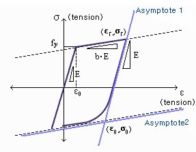
This is the steel model of Menegotto and Pinto, which was modified by Filippou et al.
.bmp)
fy: Yield strength of reinforcing steel
E: Modulus of elasticity
b: Stiffness reduction factor after yielding
Ro, a1, a2: Coefficients for shape index (R) for steel fiber constitutive model
This Stress-Strain hysteresis model is outlined as follows:
The above formula represents a curved transition from the elastic range to the yielding range.
 and
and  are normalized values and are calculated as follows:
This model has two asymptotes as shown below.
One asymptote has a slope of elastic stiffness and the other has a slope
of yielding stiffness.  is
a point intersected by two asymptotes.
is
a point intersected by two asymptotes.  is
the point where the last unloading occurred. While unloading and reloading,
these points are updated, so that the transition curve is affected.
is
the point where the last unloading occurred. While unloading and reloading,
these points are updated, so that the transition curve is affected.
R is the value that can affect the shape of the transition curve and represents the Bauschinger effect. The value of R is determined as follows:
Coefficients  are
determined from experimental hysteresis results. MIDAS uses 18.5, 0.15
and 20, respectively, as default values. These default values are suggested
in the original reference (Menegotto and Pinto,1973).
are
determined from experimental hysteresis results. MIDAS uses 18.5, 0.15
and 20, respectively, as default values. These default values are suggested
in the original reference (Menegotto and Pinto,1973).
 is a shape coefficient and
updated at every unloading.
is a shape coefficient and
updated at every unloading.
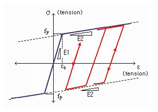
This model represents a general symmetric Bilinear model for reinforcing steel.
.bmp)
fy: Yield strength of reinforcing steel
E1: Initial stiffness of reinforcing steel
E2/E1: Ratio of stiffness after yielding to the initial stiffness
As shown in the figure below, the model behaves elastically when it is unloaded and reloaded after yielding.
Asymmetrical Bilinear Steel Model
This model has been derived from the general bilinear steel model. Stiffness after compressive and tensile yielding can be freely defined. Buckling and rupturing of reinforcing steel can be considered.
.jpg)
σy: Tensile yield strength
σcy: Compressive yield strength
ε1: Strain at compression buckling of reinforcing steel
ε2: Strain at rupturing of reinforcing steel after yielding
E1: Initial stiffness of reinforcing steel
E2: Stiffness of reinforcing steel after tensile yielding
E3: When tension becomes unloaded and reloaded in the compression zone, the E3 line limits the stiffness under compression loading.
E4: Stiffness of reinforcing steel after compressive yielding
(A negative slope can be specified by entering a negative value.)
E5: Stiffness of buckled reinforcing steel after compressive yielding
This Model can describe compressive yielding, tensile yielding, tension rupture, compression buckling, etc of reinforcing steel. The figure below shows the possible hysteresis states.
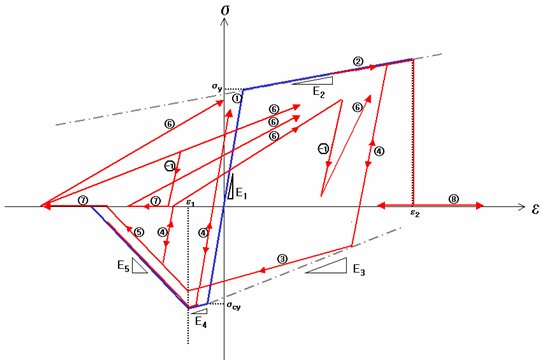
Each state is explained as follows:
Since tension behavior is the major cause of hysteresis in steel, the loading direction basically follows tension. During unloading, the loading direction changes from tension to compression, and vice-versa during reloading.
State 1: It represents the elastic behavior, and the slope is E1.
1 → 2 = Transition to yielding state. The slope is E2 under tensile yielding and E4 under compressive yielding.
State 2: It represents the state after the yielding starts, and the slope is E2.
2 → 4 = Unload and reload after yielding.
2 → 8 = Tension is sustained after yielding, and thereafter, tension rupture is caused. The stress is always ??after the rupture.
State 3: Unload
continuously and as a result the compression zone yields. The slope is
E2. E3 should be input such that the point intersecting the line E3 and
strain axis is greater than  .
.
3 → 4 = Reload. The slope is E1.
3 → 5 = As unloading continues, the compression
strain exceeds  and
compression buckling starts. The slope is E5.
and
compression buckling starts. The slope is E5.
State 4: Unloading and reloading with slope E1 (elastic stiffness)
4 → 2 = As reloading continues, the state changes to tensile yielding state. Or as unloading continues, the state changes to compressive yielding state.
4 → 3 = As unloading continues, compressive yielding occurs. It can be assumed that compressive yielding occurs at the intersection with line E3.
4 → 5 = As unloading continues, compression buckling starts.
State 5: When compression strain exceeds buckling strain, buckling of reinforcing steel takes place. The slope is E5.
5 → 4 = Reloading continues during compression buckling.
5 → 7 = As compression is sustained, the reinforcing steel undergoes complete compression buckling. The stress becomes ??at compression during and after State 7.
State 6: Reload after compression buckling.
Reloading will progress towards  before tensile yielding
occurs. Reloading will progress towards the maximum point in the tension
zone after tensile yielding occurs.
before tensile yielding
occurs. Reloading will progress towards the maximum point in the tension
zone after tensile yielding occurs.
6 → 2 = As reloading continues, tensile yielding takes place.
6 →-1 = Unload while reloading.
State 7: Once complete compression buckling occurs, further compressive stresses cannot be generated. Although compressive stress becomes ?? it can still resist tension.
7 → 6 = Reloading occurs and progresses towards the maximum tension point.
State 8: Once tension rupture occurs, further tensile stresses cannot be generated, and neither will compressive stresses be generated.
State ?: Unload while reloading after compression buckling (State 6). The slope is E1 (elastic stiffness).
-1 → 6 = Reloading progresses towards the maximum tension point.
-1 → 7 = Unloading and the subsequent transition to complete compression buckling
As stated above, this model considers the various states and transitions. If the user is familiar with this model and applies the experimental parameters properly, it can be a very efficient tool. However, the user must use caution when using this model for limit states, such as tension rupture and compression buckling, as the resistance becomes zero.
This model represents a Trilinear model of three slopes. The hysteresis can be defined by the stress-strain relationship and the stress-stiffness reduction ratio relationship.
When unloading and reloading, the model behaves elastically.
.bmp)
Stress-Strain Definition
Stress-Stiffness reduction ratio Definition
σ1y: First yield strength in tension
σ2y: Second yield strength in tension
σ3y: Stiffness after second tensile yielding (required for K3 calculation)
σ'1y: First yield strength in compression
σ'2y: Second yield strength in compression
σ'3y: Stiffness after second compressive yielding (required for K5 calculation)
ε1y: Strain at first yielding in tension
ε2y: Strain at second yielding in tension
ε3y: Strain after second tensile yielding (required for K3 calculation)
ε'1y: Strain at first yielding in compression
ε'2y: Strain at second yielding in compression
ε'3y: Strain after second compressive yielding (required for K5 calculation)
K: Initial stiffness of reinforcing steel
K2/K1: Ratio of stiffness after first tensile yielding to the initial stiffness
K3/K1: Ratio of stiffness after second tensile yielding to the initial stiffness
K4/K1: Ratio of stiffness after first compressive yielding to the initial stiffness
K5/K1: Ratio of stiffness after second compressive yielding to the initial stiffness
Note
When ε1y~ε'3y are entered in the 'σ - ε' input method, and the 'σ - α'
input method is selected, K1, K2/K1, K3/K1, etc. are automatically calculated.
Also the reverse calculation is automatically done.

.bmp)
 : Ratio of the volume of hoop reinforcement to the volume
of concrete core measured to outside of stirrups
: Ratio of the volume of hoop reinforcement to the volume
of concrete core measured to outside of stirrups  : Yield strength of stirrup steel
.bmp)

.bmp)
 : Width of concrete core measured to outside of stirrups