Function
Check the story drifts due to static and dynamic loads in a spreadsheet format table.
"Story Shear Force Ratio" in "Model/Building/Control Data" must be checked for this function, which is checked as the Default.
The types of story drifts, which can be checked in Story Drift Table, are as follows:
1. Maximum Drift
2. Drift at the Center of Mass
3. Average Drift of Vertical Elements at each floor
4. Drift of Selected Node Line, which passes through a node selected by user vertically
5. Average Drift of Extreme Nodes Lines
6. Shear Weighted Average Drift of Vertical Elements
When "Story Shear Force Ratio>Consider Story Module" is checked in the "Model/Building/Control Data", accurate shear forces can be obtained for the story having the overlapping Module.
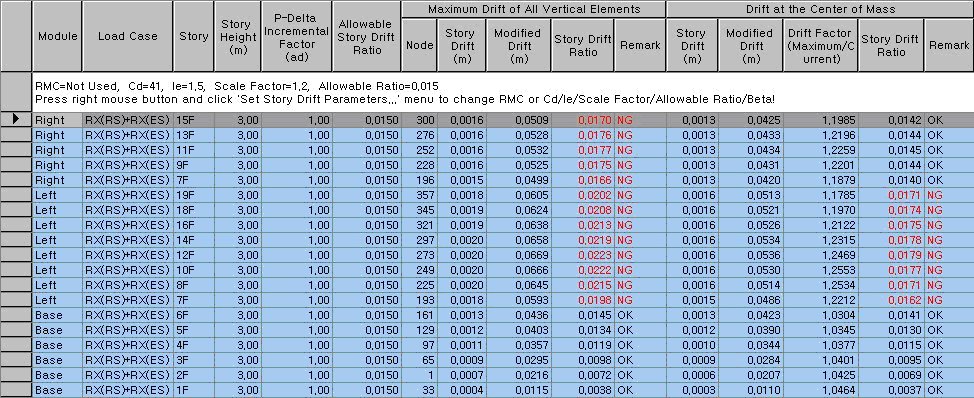
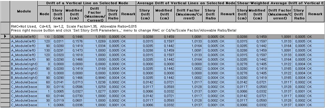
When Modules are defined in Results > Result Tables > Story > Define Module, the Module data is displayed in the first column of the table.
When the ratios exceed the allowable limit, they appear in red and “Irregular” is printed in the Remark.
Table Tool in MIDAS/Gen offers a variety
of powerful built-in functions. Refer to the following items for detail
directions:
Basic directions (Cell motion, selection, size control, etc.)
Data manipulation (Add, delete, modify data, etc.)
Copy/Paste data using clipboard
Supplementary functions by Table types
Call
From the Main Menu select Results > Result Tables > Story > Story Drift.
Select Result Tables > Story > Story Drift in the Tables tab of the Tree Menu.
Usage
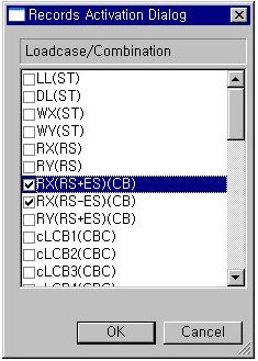
From Records Activation Dialog, select the load cases for which story drifts will be calculated.
Note
Refer to Results Table
of "Usage of Table Tool"
for the usage of Records Activation Dialog.
Record Activation dialog
box
Refer to Usage of Table Tool and check the following data:
 When
Modules are not defined
When
Modules are not defined
Drift(X): Story drift in GCS X-direction (Click lower left tab)
Drift(Y): Story drift in GCS Y-direction (Click lower left tab)
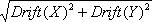
Drift(Combined):
Combined story drift of both GCS X, Y-directions (Click lower left tab)
Load Case: Unit load case/combination
Story: Story ID
Story Height: Story Height
P-Delta Incremental Factor(ad): When P-Delta analysis is performed, the incremental factor becomes 1.0 irrespective of calculation results.
Note
For a story drift used for calculating the P-Delta Incremental Factor (ad),
the �Maximum Drift of All Vertical Elements?is used. (Story drift as per
�Story Drift Calculation Method?is not used in calculating the P-Delta
Incremental Factor (ad) since the values are different depending upon
the method used.)
Allowable Story Drift Ratio
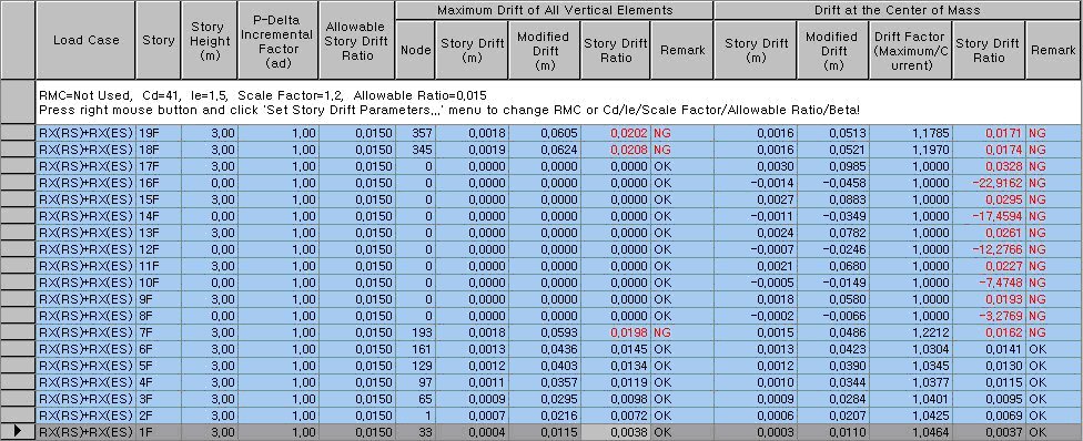
1. Maximum Drifts of All Vertical Elements
Maximum drifts are produced for each story.
Node: Node numbers corresponding to the maximum story drifts at each story level
Story Drift: Incremental lateral displacement over two consecutive story levels
Modified Drift: Incremental factor for P-Delta effect * Deflection Amplification Factor * Story Drift * Scale Factor / Importance Factor
Story Drift Ratio: Modified Drift / Story height
Remark: Acceptance of story drift ratio relative to the allowable story drift ratio
2. Drift at the Center of Mass
Difference in lateral displacements at the centers of mass at top and bottom ends is produced.
Drift Factor (Maximum / Current): Maximum story drift / Story drift at center of mass
Refer to Maximum Drift for the remainder.
3. Average Drift of Vertical Elements
Average story drift at a corresponding story is produced.
Drift Factor (Maximum / Current): Maximum story drift / Drift at the selected node line
Refer to Maximum Drift for the remainder.
Note
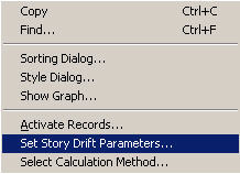
The items 3, 4, 5 & 6 are produced by right-clicking the mouse on the
table followed by selecting specific items in 'Select Calculation Method'.
4. Drift of a Vertical Line on Selected Node
Story drifts at a user selected node and the nodes, which are located on the vertical line passing the selected node, are produced.
Drift Factor (Maximum / Current): Maximum story drift / Story drift at user-selected node
Refer to Maximum Drift for the remainder.
5. Average Drift of Vertical Lines on Selected Nodes
Average story drifts of building column lines selected by the user are produced. The column lines here should be selected at the extremities of the building plan.
Drift Factor (Maximum / Current): Maximum story drift / Average story drift of the building plan extremities
Refer to Maximum Drift for the remainder.
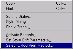
Context Menu (Select Calculation Method)
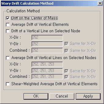
Story Drift Calculation Method dialog box
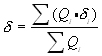
6. Shear Weighted Average Drift of Vertical Elements
Shear forces in the vertical members are reflected into the story drifts.
The shear weighted average drift is produced only when the 'Story Shear Force Ratio of Member' option is applied in Model>Building>Control data.
Story Drift::
 : member shear force at story
 : horizontal displacement
of each story member
: horizontal displacement
of each story member
Drift Factor (Maximum / Current): Maximum story drift / shear weighted average story drift
Refer to Maximum Drift for the remainder.
7. Context Menu
The user provides the data for calculating modified story drifts and P-Delta incremental factors. These are required values for generating the table. When Table is invoked, the set Story Drift Parameters window is executed first.
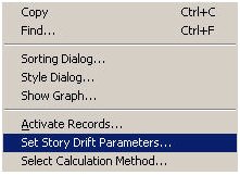
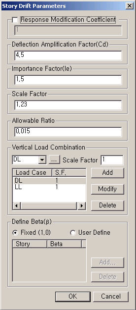
Context Menu (Set Story Drift Parameters)
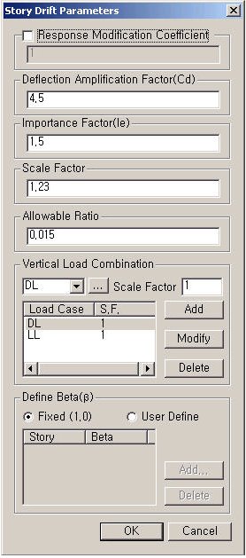
Set Story Drift Parameters dialog box
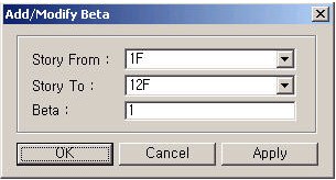
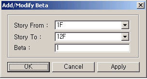
Modify Beta dialog box
Response Modification Coefficient
Deflection Amplification Factor
Importance Factor
Scale Factor: Cm, Scale-up Factor
Vertical Load Combination: Define a vertical load condition to consider the P-Delta effect.
Define Beta: Design Shear Force/Shear Capacity at a story in question, which can be defined by the user for each story
Note
All the items other than Response
Modification Coefficient are applied
only for IBC 2000 and KBC 2005.
When Modules
are defined
The Module column is generated only when
the Modules are defined. Story drifts are calculated as per the following
Note.
Drift(X): Story drift in GCS X-direction (Click lower left tab)
Drift(Y): Story drift in GCS Y-direction (Click lower left tab)
Drift(Combined):
Combined story drift of both GCS X, Y-directions (Click lower left tab)
Note
Method of calculating Story Drift for each Module
Module Example
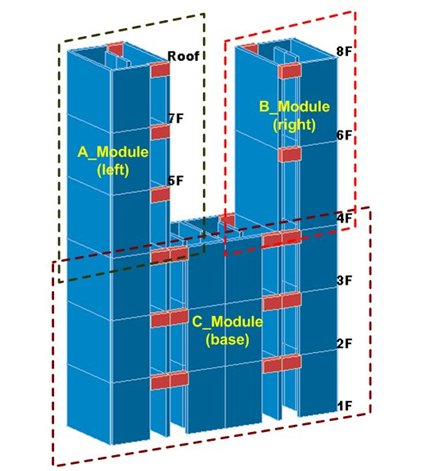
1. Story drifts for the top floors of each Module are not generated.
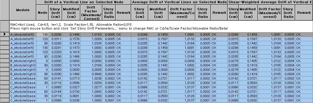
2. Maximum Drift of All Vertical Elements
Drift at 4F of A_Module (left) is the maximum of story drifts for all the vertical elements at 4F (differences between the displacements at 4F and 5F). Drift at 4F of B_Module (right) is the maximum of story drifts for all the vertical members at 4F (differences between the displacements at 4F and 6F). Drift at 4F of C_Module (base) is not generated.
3. Drift at the Center of Mass
1) For a story assigned with Story Diaphragm:
The drift at 4F of A_Module (left) is the difference between the displacement at a point on 4F, which is generated when the Diaphragm Center (Mass Center) of 5F is projected on 4F, and the displacement at Mass Center of 5F. The drift at 4F of B_Module (right) is similarly calculated. A projected point on 4F is assumed to be included in the Diaphragm of 4F when calculating the displacement.
2) For a story without Story Diaphragm:
Average story drifts of vertical elements are used. To consider the case when specific wall elements are divided into smaller elements, first obtain the average drifts for each area and then obtain an average of all the average drifts.
Ex) When 5F is assigned with a diaphragm and 4F not assigned with a diaphragm (slab is modeled by using plate elements), the drift is the difference between the displacement at diaphragm center of 5F and the average displacement of vertical elements at 4F.
Module: Module name is defined in Define Module
Load Case: Unit load case/combination
Story: Story ID
Story Height: Story Height
P-Delta Incremental Factor(ad): When P-Delta analysis is performed, the incremental factor becomes 1.0 irrespective of calculation results.
Note
For a story drift used for calculating the P-Delta Incremental Factor (ad), the “Maximum Drift of All Vertical Elements” is used. (Story drift as per “Story Drift Calculation Method” is not used in calculating the P-Delta Incremental Factor (ad) since the values are different depending upon the method used.)
Allowable Story Drift Ratio
1. Maximum Drifts of All Vertical Elements
Maximum drifts are produced for each story.
Node: Node numbers corresponding to the maximum story drifts at each story level
Story Drift: Incremental lateral displacement over two consecutive story levels
Modified Drift: Incremental factor for P-Delta effect * Deflection Amplification Factor * Story Drift * Scale Factor / Importance Factor
Story Drift Ratio: Modified Drift / Story height
Remark: Acceptance of story drift ratio relative to the allowable story drift ratio
2. Drift at the Center of Mass
Difference in lateral displacements at the centers of mass at top and bottom ends is produced.
Drift Factor (Maximum / Current): Maximum story drift / Story drift at center of mass
Refer to Maximum Drift for the remainder.
3. Average Drift of Vertical Elements
Average story drift at a corresponding story is produced.
Drift Factor (Maximum / Current): Maximum story drift / Drift at the selected node line
Refer to Maximum Drift for the remainder.
Note
The items 3, 4, 5 & 6 are produced by right-clicking the mouse on the
table followed by selecting specific items in 'Select Calculation Method'.
Story drifts at a user selected node and the nodes, which are located on the vertical line passing the selected node, are produced.
Drift Factor (Maximum / Current): Maximum story drift / Story drift at user-selected node
Refer to Maximum Drift for the remainder.
5. Average Drift of Vertical Lines on Selected Nodes
Average story drifts of building column lines selected by the user are produced. The column lines here should be selected at the extremities of the building plan.
Drift Factor (Maximum / Current): Maximum story drift / Average story drift of the building plan extremities
Refer to Maximum Drift for the remainder.
Context Menu (Select Calculation Method)
Story Drift Calculation Method dialog box
6. Shear Weighted Average Drift of Vertical Elements
Shear forces in the vertical members are reflected into the story drifts.
The shear weighted average drift is produced only when the 'Story Shear Force Ratio of Member' option is applied in Model>Building>Control data.
Story Drift::
: member shear force at story
: horizontal displacement
of each story member
Drift Factor (Maximum / Current): Maximum story drift / shear weighted average story drift
Refer to Maximum Drift for the remainder.
7. Context Menu
The user provides the data for calculating modified story drifts and P-Delta incremental factors. These are required values for generating the table. When Table is invoked, the set Story Drift Parameters window is executed first.
Context Menu (Set Story Drift Parameters)
Set Story Drift Parameters dialog box
Modify Beta dialog box
Response Modification Coefficient
Deflection Amplification Factor
Importance Factor
Scale Factor: Cm, Scale-up Factor
Vertical Load Combination: Define a vertical load condition to consider the P-Delta effect.
Note
All the items other than Response
Modification Coefficient are applied
only for IBC 2000 and KBC 2005.